Advertisement
Quick Links
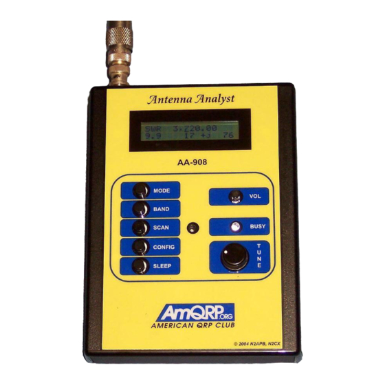
~ Assembly Manual ~
Micro908
Antenna Analyst
The Micro908 is a flexible and re-usable control platform for ham radio projects. The Micro908
platform is designed to be easily operated on the bench as well as in the field. It is comprised of a
single 5" x 5" printed circuit board containing all components, connectors, controls, LCD, and two
daughtercards. The plastic enclosure contains an 8-cell AA battery back enabling convenient field
use. A number of standard ham radio peripherals may be connected to the Micro908: antenna,
paddles, a PC-style keyboard, headphones, an audio line to drive an SSB transceiver, a keyline to
drive a transmitter, your rig's audio in/out signals, and custom control lines via an auxiliary jack. The
first major software available for the Micro908 platform is the Antenna Analyst – an instrument that
automatically determines SWR and complex impedance characteristics of an HF antenna system.
Advanced features of DDS frequency control, LCD tuning, PC data collection and plotting, numerous
operating modes and easy software upgradability make this instrument attractive for homebrewers and
antenna enthusiasts.
Micro908 Antenna Analyst "Assembly Manual", v2
1
Copyright 2004, G. Heron, N2APB
Advertisement
Troubleshooting

Summary of Contents for AmQRP AA-908
- Page 1 ~ Assembly Manual ~ Micro908 Antenna Analyst The Micro908 is a flexible and re-usable control platform for ham radio projects. The Micro908 platform is designed to be easily operated on the bench as well as in the field. It is comprised of a single 5”...
-
Page 2: Table Of Contents
Please let us know how it works out for you or if you have any questions along the way. We thank you for purchasing the Micro908 Kit from the AmQRP Club and we wish you good luck in building and using it! Sincerely yours, “The Micro908 Team”... -
Page 3: Section 2: Parts Inventory
Section 2: Parts Inventory Carefully review the contents of each parts bag and component supplied in the kit to ensure that you have everything needed at the start of the project. If a part is missing, please contact us by email and we’ll get it out to you right away. Surface Mount Components Sheet Micro908 Antenna Analyst “Assembly Manual”, v2 Copyright 2004, G. - Page 4 Controls & Connectors Bag BNC, pcb mount Serial port connector, DB9F Rotary Encoder Coaxial pow er connector, 2.1mm Socket, 1x12 pos'n (DSP out) Socket, 2x10 position, (DSP in) Mini-DIN, 6 pos'n (KBD) J6, J7, J12 Audio jack, 1/8", pcb mount Socket, 1x8 pos'n, right angle Mini-Din, 8 pos'n (AUX) Jumper, Flexstrip, (LCD)
- Page 5 Semiconductor Bag Voltage regulator, 3-terminal, 7805 Memory, SEEPROM, 512Mb U3, U4 IC, Op Amp, LMC6484, SOIC IC, Audio Amp, LM386, SOIC IC, Level Translator, TC7SET08F, SOIC LED1 LED, T1-3/4 (BUSY) Shunt shunt, 0.1", 2 pos'n D7, D8, D9 Diode, Schottky, 1N5817, DO-41 VR1 - DDS Option Voltage Regulator, 78L08, 8V (optional, for use w ith regarga Transistor, NPN, 2N3904, TO92...
- Page 6 DSPx Daughtercard Bag (Optional) DSPx DSPx for Micro908 assembly DDS Daughtercard Kit Bag (Optional) DDS Kit DDS Daughtercard Kit Keyboard Cable Bag (Optional) Cable Keyborad extension cable (6') Keyboard (Optional) Keyboard Dauphin Mini Keyboard Enclosure (Optional) Enclosure Pac-Tec LH-57 Enclosure (pre-drilled) Micro908 Antenna Analyst “Assembly Manual”, v2 Copyright 2004, G.
- Page 7 Section 3: PC Board Preparation Meet the Micro908 PC Board! You should become familiar with the orientation nomenclature that we’ll be using throughout this manual. Top, “Component” Side Left Right Bottom, “Ground”, “Controls” Side Left Right Micro908 Antenna Analyst “Assembly Manual”, v2 Copyright 2004, G.
-
Page 8: Section 4: Installing The Surface Mount Components
Section 4: Installing the Surface Mount Components Preparing for the job The key to being successful with any construction project is selecting and using the proper tools. For projects using SMT (Surface Mount Technology), the tools are easy to find. A magnifying lamp is essential for well-lighted, close-up work on the components. - Page 9 First corner pin of surface mount IC being attached. Solder wick easily absorbs excess solder between pins. (IC shown being attached here is the DDS chip onto the DDS Daughtercard. The techniques are the same for the Micro908 ICs.) Using the Component Layouts During Assembly A helpful practice to develop is to mark the supplied Layout diagram as you install each component.
- Page 10 [ ] 4 R37, R38, R39, R40 Resistor, 5.1K, SMT, 1206 [ ] 12 R1, R2, R3, R4, R5, R17, Resistor, 10K, SMT, 1206 R18, R22, R23, R27, R42, R48 2) Install components from Resistor Card 2 Using the Component Layout Diagram in Appendix A as a guide, install the SMT components from the Resistor Card 2. Check off each row as you complete installing those components.
- Page 11 5) Install components from Semiconductor Bag Using the Component Layout Diagram in Appendix A as a guide, install the components from the Semiconductor Bag. Check off each row as you complete installing those components. [ ] 1 Voltage regulator, 3-terminal, 7805 [ ] 1 Heatsink - TO220 (From Controls Bag) Position the voltage regulator over the mounting hole to determine where to bend the three leads so they can be inserted to...
- Page 12 Section 5: Installing Parts from the Controls and Connectors Bag 1) Install Pinheaders & Sockets Using the Component Layout Diagram in Appendix A as a guide, install all pinheaders and strip sockets on the Component side of the board … [ ] 2 P1, P2 Pinheader, 2x34 (HC908)
- Page 13 2) Install Thru-hole Components Using the Component Layout Diagram in Appendix A as a guide, install all thru-hole components on the Component side of the board … [ ] 3 C&, C33, C34 Capacitor, 1 uF, Electrolytic Note that an engineering mod has already been done to the board in the positions for C33 and C34 to correct for a pad layout error.
- Page 14 4) Install Controls Using the Component Layout Diagram in Appendix A as a guide, install all controls on the Bottom/Controls/Ground side of the pc board. It is really important to install these components on the Bottom/Controls side of the pc board. Double- check the Completed PC Board Assembly photos in Appendix E to ensure that you are inserting these connectors to the proper side of the pc board.
- Page 15 [ ] 1 SPKR Speaker, miniature, 32-ohm When soldering this component in place, be careful to orient the leads so the pin marked with a ‘+’ is placed in the hole clsest to the silkscreened ‘+’. Be sure not to apply too much heat while soldering, as the plasic of fthe speaker body can easily melt and deform.
- Page 16 5) Install LCD Using the Component Layout Diagram in Appendix A as a guide, install the LCD on the Bottom/Controls/Ground side of the pc board … [ ] 1 Display, LCD, Hantronix, 16x2 STN, GRAY [ ] 1 Jumper, Flexstrip, (LCD) You’ll use the 16-wire flexible jumper W1 to connect the LCD to the pcb, as shown in the photos below.
-
Page 17: Section 6: Power-Up And Test
Section 6: Power-up and Test [ ] Prepare for the Tests When first ready to apply power to the newly-assembled Micro908, position the pc board on the bench (without the enclosure) and with the LCD and controls side facing up. This will enable you to more easily get to the components and you can spot gross problems (like exploding capacitors, smoking regulators, etc.) should they occur. -
Page 18: Section 8: Troubleshooting
This is okay for now. If the LED did not illuminate at the start of the Scan, and turn off at the end of the Scan, make a note to visit the Troubleshooting section later on. [ ] Press the CONFIG Pushbutton to get into the Configuration Menus The CONFIG pushbutton may be pressed at any time to access the Configuration menus. - Page 19 [ ] Calibrate the Micro908 reflectometer channels for gain You will need to calibrate the Micro908 Antenna Analyst when first constructed. The instrument may also need to be recalibrated later, such as when a new software update is available that changes the way in which calibration data are used, or when the level of the DDS signal source changes in any regard.
- Page 20 We have a spectrum analysis screen shot representative of a well-calibrated Antenna Analyst on the Micro908 project page at http://www.amqrp.org/kits/micro908. It shows the second harmonic >30 dB down from the fundamental, which is a very good and important characteristic of the DDS signal generated in the instrument.
- Page 21 Section 7: Installing the PCB in the Enclosure Now that the functional tests are complete, you can finish the final assembly of the Micro908 by installing it into the enclosure. (NOTE: The enclosure is an optional item and may not have been purchased. If this is the case, you are done!) Refer to the Mechanical Assembly diagram in Appendix E for a detailed “exploded view”...
- Page 22 [ ] Apply Overlay Label to Drilled End Panel Locate the black overlay with white labels and carefully apply it to the drilled end panel. Carefully peel back the protective paper from the sticky side off the overlay and lay it down on the side of the end panel that is “raised” around the edges – that is, the fully-flat side of the end panel will end up being on the inside of the Micro908, so you want to apply the overlay label to the outside surface.
-
Page 23: Troubleshooting
[ ] Install the Bottom Shell of the Enclosure Place the bottom black plastic shell of the enclosure in place and use the four ¾” self-tapping screws to secure it to the top shell. [ ] Install Rubber Feet Peel off the four rubber feet and apply them to the corners of the enclosure’s bottom shell. [ ] It’s “Miller Time”! Assembly of the Micro908 is complete. - Page 24 Make sure you have your battery polarity proper with the wires going to the circuit board, and be sure the connector supplying external power is wired with positive-to-center on the mating plug to J4. If either connection is reversed, your board will not be damaged, but it won’t receive the necessary voltage to make it work.
- Page 25 Voltage Charts Typical LCD display of Reflectometer readings in Calibration for the three calibration conditions of Open circuit load, Short circuit load, and 50-Ohm circuit: Open Short 50-ohm Typical voltages for the four Reflectometer op amp channels in the three calibration conditions of Open circuit load, Short circuit load, and 50-Ohm circuit: OPEN CIRCUIT Reflectometer output...
- Page 26 APPENDIX A: Micro908 Parts List SURFACE MOUNT COMPONENTS SHEET Resistor Card 1 Resistor, 10, SMT, 1206 R11, R12, R14 Resistor, 49.9, SMT, 1206, 1% Resistor, 330, SMT, 1206 Resistor, 1K, SMT, 1206 Resistor, 4.3K, SMT, 1206 Resistor, 4.7K, SMT, 1206 R37, R38, R39, R40 Resistor, 5.1K, SMT, 1206 R1, R2, R3, R4, R5, R17, R18, R22, R23, R27, R42,...
- Page 27 Controls & Connectors Bag BNC, pcb mount Serial port connector, DB9F Rotary Encoder (ENC) Coaxial DC power connector, 2.1mm Socket, 1x12 pos'n (DSP out) Socket, 2x10 position, (DSP in) Mini-DIN, 6 pos'n (KBD) Audio jack, 1/8", pcb mount J6, J7, J12 Socket, 1x8 pos'n, right angle (DDS card) Mini-Din, 8 pos'n (AUX) Jumper, Flexstrip, (LCD)
- Page 28 PCB Bag PC Board HC908 Daughtercard Bag (Optional) HC908 HC908 Daughtercard assembly DSPx Daughtercard Bag (Optional) DSPx DSPx for Micro908 assembly DDS Daughtercard Kit Bag (Optional) DDS Kit DDS Daughtercard Kit DDS Chip Card (Optional) AD9854BRS DDS chip for DDS Daughtercard Kit Keyboard (Optional) Keyboard Dauphin Mini Keyboard...
- Page 29 Programming Port Paddle P2- 5 P1-9 P2- 8 P2- 7 P1-7 P2- 10 P2- 11 4.3K P2- 14 P2- 15 P2- 18 Data P2-25 P2- 29 Keyboard P2-34 P2- 32 P2- 31 HC908 Daughtercard Rotary P1-29 Encoder P1-28 HLD/ P1-21 SEEPROM P1-30 512 kb...
- Page 30 Compensation & Buffer Amplifiers Daughtercard from HC908: J10-1 port F2 Load J10-2 port F1 Clock J10-3 port F0 Data J10-4 to HC908 5V out port B4 71.5K J10-5 220K J10-6 RF Out A 1N5711 221K J10-7 RF Out B J10-8 to HC908 71.5K port B1...
- Page 33 APPENDIX D: Completed PC Board Assembly Top/Component Side Bottom/Controls Side Micro908 Antenna Analyst “Assembly Manual”, v2 Copyright 2004, G. Heron, N2APB...
- Page 34 APPENDIX E: Mechanical Assembly Micro908 Antenna Analyst “Assembly Manual”, v2 Copyright 2004, G. Heron, N2APB...
-
Page 35: Appendix F: Quick Reference Sheet
Micro908 “Antenna Analyst” Quick Reference Sheet Mode Band Scan Config Save changes to EEPROM Exit Scanning … Impedance 1-10 MHz & Exit Setup “Busy” LED on 10 Hz Turn dial to during scan of selected 100 Hz select size Step Size band limits with selected 1 kHz Capacitance... -
Page 36: Appendix G: Loading New Software Into The Micro908
USAGE 1. Download the latest Micro908 software from the project website located at http://www.amqrp.org/kits/micro908 Save the S19 file in a known location on your PC (e.g., your desktop folder.) The S19 file is the file with the “.s19” extension to its filename. This is a text representation of the binary image to be loaded onto the Micro908. -
Page 37: Appendix H: Making A Dummy Antenna For Testing
APPENDIX H: Making a Dummy Antenna for Testing You will find it convenient to have a “dummy antenna” to use in testing the Micro908 Antenna Analyst operation. A dummy antenna is simply a 3-component circuit that is resonant at a specific frequency and has a purely resistive characteristic at that resonant frequency.
Need help?
Do you have a question about the AA-908 and is the answer not in the manual?
Questions and answers