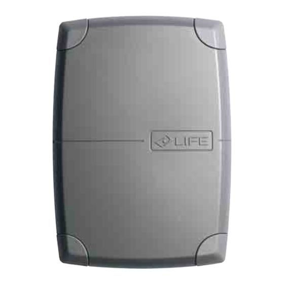
Summary of Contents for SAMT GE UNI R DL
- Page 1 GE UNI R DL GE UNI RS DL GE UNIR DL CONTROL UNIT FOR TWO-LEAF GATES INSTRUCTIONS AND WARNINGS FOR INSTALLATION, USE AND MAINTENANCE...
- Page 2 STANDARD INSTALLATION Tab. 1: Components and devices of a typical GE UNI R DL automation. Tab. 2: Description of the content of a GE UNI R DL control unit pack.
- Page 3 GEBOX ASSEMBLY INSTRUCTIONS.
- Page 4 List of electric cables The cables needed may vary depending on the installation and type and quantity of devices installed. The cables used in the installation must be IEC 60335 compliant. Connection Pos. Type of cable Electricity supply line 3x1,5 mm cable Power supply FUSES...
- Page 5 GE UNI R DL AERIAL RG58-50ohm N.C. N.O. N.O. N.O. STEP For PHOTO and PHOTO1 N.C. PHOTO1 input functions N.C. PHOTO see page 7 12 Vac 15VA ELECTRIC LOCK 24 Vac 3W max INDICATOR LIGHT OUTPUT 24 Vac 200 mA max...
- Page 6 PROGRAMMING THE CONTROL BOARD STOP PLATES Ensure that the open and close stop plates are set to the correct position PROGRAMMING THE CONTROL UNIT SINGLE MOTOR - In the case of a single gate installation connect the motor into terminals 20-21-22 before programming enter the options menu 2 and select single motor activated (led 4 DEFINING THE STOP PLATES ISOLATION...
- Page 7 DELETING RADIO CONTROL TRANSMITTERS RADIO CONTROL MANAGEMENT The control unit is fitted with a built-in radio receiver with a 1 channel 1000-code memory, with a 433.92 MHz frequency with LIFE Rolling Code and Auto code encoding. Resetting an initialised radio control DELETING A SINGLE RADIO TRANSMITTER DELETING A SINGLE RADIO TRANSMITTER •...
- Page 8 PROGRAMMING MENUS PROGRAMMING MENUS AUTOMATIC CLOSING 3.1.2 Automatic reclosure In this mode by pressing the start button or In this mode by pressing the start button or Automatic reclosure is activated after a preset PAUSE TIME. radio transmitter the automation changes it In this mode, by pressing the ‘STEP’...
- Page 9 • • Press the force button (bottom left) and the FORCE FORCE 3.2.3 Force The force function regulates the thrust and the speed of the automation. Press the red LED (LEFT) switches on. Press to set the various force values. LEDS ON FORCE VALUE Minimum...
- Page 10 MANUAL PROGRAMMING 3.3.4 Programming Manual POSITION THE GATE AT 45 DEGREES POSITION THE GATE AT 45 DEGREES Position the leaf gates at 45° • • Press the start button for 5 seconds, the fi rst of the 5 top Press the start button for 5 seconds, the fi rst of the 5 top led’s light and fl...
-
Page 11: General Information
GENERAL INFORMATION It is strictly forbidden to copy or reproduce this instruction manual without written permission to do so and subsequent verification by LIFE home integration. Translation into other languages of all or part of the manual is strictly forbidden without previous written authorisation from and subsequent verification by LIFE home integration. All rights on this document are reserved. LIFE home integration will not accept responsibility for damage or malfunctions caused by incorrect installation or improper use of products and Users are therefore recommended to read this manual carefully LIFE home integration will not accept responsibility for damage or malfunctions caused by the use of the automation together with the devices of other manufacturers;... - Page 12 TESTING AND TRIAL RUN • The testing and trial run must be performed by a COMPETENT PERSON supervised and aided by a PROFESSIONAL FITTER. It is the responsibility of the person who tests and sets up the automation (of which the control unit is a part) to perform the checks required in accordance with the risks existing and to check conformity with the relevant legislation and standards, in particular with EN standard 12445, which governs the methods for performing trials on gate automations and EN standard 12453 that specifies the performance requisites concerning safety of use.
-
Page 13: Maintenance
MAINTENANCE 10.1 Maintenance instructions and warnings • Once the automation has been tested, the parameters set must not be altered. If further adjustments (e.g. alterations to the voltage value) are made, ALL THE CHECKS REQUIRED FOR TESTING AND COMPLIANCE WITH STANDARDS MUST BE REPEATED. •... -
Page 14: Declaration Of Conformity
Declaration of conformity under Directive 98/37/EC, appendix II, part B (Manufacturer’s Declaration of CE Conformity) LIFE Home Integration Via S.Pertini 3/5 31014 COLLE UMBERTO (TV) declares that the following product: GEUNIR DL control unit satisfies the essential requisites established in the following directives: •... - Page 15 Address: Factory 19, 5 Lyn Parade PRESTONS NSW 2170 Telephone: (02) 9607 4100 Email: sales@SAMT.com.au www.samtgatemotors.com.au...

Need help?
Do you have a question about the GE UNI R DL and is the answer not in the manual?
Questions and answers