
Summary of Contents for LightSymphony LS30900BSR
- Page 1 Base Station Operating Manual & Installation Guide MODELS: LS30900BSR & LS30950WIFI (WiFi version) Create A Scene Outdoors !
-
Page 2: Table Of Contents
Index SECTION 1 – Installation Installation Location SECTION 2 - Initial Setup Front Panel Navigating The Menus Setting Time / Date Setting Dusk/Dawn location Setting Dusk / Dawn Time SECTION 3 –Timer Setup Introduction Setting Timers (1-6) 10-12 SECTION 4 –Colour Light Show Coilour Light Show Light Show Setup... - Page 3 Index SECTION 5 – Interfacing (Advanced Setup Introduction Digital Trigger Input Digital On/Off Digtial Trigger mode Digtial Trigger with Timers Wifi Version Only (Model LS30950WIFI)... Serial Port 18-19 Serial Port with Lutron 20-21 WiFi Interface Joining an Existing WiFi network Creating an Ad-Hoc Network SECTION 6 –...
-
Page 4: Installation
Section 1 Installation Installation The Light Symphony base-station is a wireless device. This means it receives commands from the remote control and is able to send control ’messages’ to the lighting modules in the garden using its antenna only. No electrical connection is required except the 9V power adapter. -
Page 5: Location
Section 1 Installation Location Locating the base-station in the best position is important and the diagram below shows why. A key function of the base-station is to ‘echo’ commands received from the remote control(s) to the garden. This creates a very reliable system because the base-station and Lighting Control Modules don‘t move, which makes the signal-path constant and therefore consistent, meaning it will always work! Remote... -
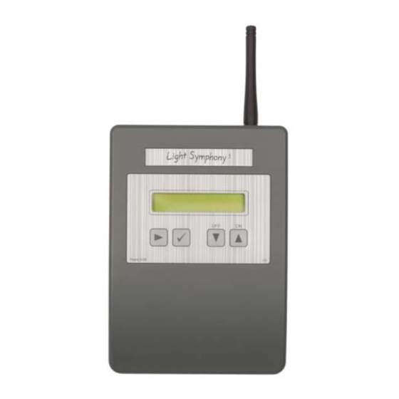
Page 6: Front Panel
Section 2 Initial Setup Front Panel 9VDC Power Interface Port Serial interface LCD Display NAVIGATE Navigates the menu OK / STORE Store settings DOWN key (All Area’s OFF) UP key (ALL Area’s ON) -
Page 7: Navigating The Menus
Section 2 Initial Setup Navigating The Menu The base-station has many functions but all are easily configured from the simple key- pad. The list below shows all the configurable options in the order in which they are displayed; Set Time / Date Set Location Set Dusk / Dawn Set Timer 1... -
Page 8: Initial Setup
Section 2 Initial Setup Setting the Time / Date Navigate to the time/date menu by pressing the “ ” key once. The display will change to show ... Press Set Time/Date Press the “ ” key to enter the Time/Date menu. The display will change as shown below. - Page 9 Section 2 Initial Setup Dusk / Dawn Time & Location The base-station includes an astronomical clock which calculates Dusk and Dawn times throughout the year. This can be useful for setting timers; for example you may like the lighting to switch on (as it gets dark) at dusk, and switch off again at 11pm. In this case, the ‘on’...
-
Page 10: Setting Dusk / Dawn Time
Section 2 Initial Setup Setting Dusk / Dawn Time Although the base-station calculates the precise dusk and dawn times for your location, you may prefer your lighting to come on slightly before sunset (dusk) or slightly after. Similarly, you may prefer the lights to go off just after sunrise (dawn) or just before. You can easily modify the Dusk and Dawn times to suit your preference using the Dusk/Dawn menu. -
Page 11: Introduction
Section 3 Timer Setup Introduction The base-station contains 6 powerful and independent timers. Each timer may be configured separately to control different aspects of your garden. The timers can be used to control an individual ‘Area’ of your garden or the whole garden together (ALL). - Page 12 Section 3 Timer Setup Setting Timer 1 (to 6) ...continued Press the “ ” key to enter the ‘Timer 1 (to 6)’ menu. The display will change to show… Timer Type Every Day Use the UP / DOWN keys to choose the timer ‘type’ you prefer from the list on page 10 and then press the “...
- Page 13 Section 3 Timer Setup Setting Timer 1 (to 6) ...continued It is also possible to configure the timer for a specific length of time. For example, to switch on at sunset (Dusk) for 3 hours. In this example, since the on-time changes throughout the year, the off-time will track these changes ensuring the lights are only on for 3 hours.
- Page 14 Section 4 Colour Light Show Colour Light Show The base-station is the control hub for Light Symphony’s Colour Light Show. The Light Show is for controlling colour RGB (red/green/blue) lights and can wirelessly synchronise the speed, timing and colour of any number of LEDs. To set- up a ‘Light Show’...
-
Page 15: Light Show Setup
Section 4 Light Show Colour Light Show set up To configure the Light Show to your preference, navigate to the ‘Set Light Show’ menu by pressing the “ ” key then pressing the DOWN key ten times. The display will change to show; Press Set Light Show Press the “... -
Page 16: Introduction
Section 5 Interfacing – Advanced Setup Introduction The base-station provides several interface options allowing connection to third party equipment. Digital Trigger Input Serial Port* WiFi Network* *NOTE The serial port and Wifi interfaces are only available on the WiFi version of the base-station Digital Trigger Input The base-station includes a low-voltage trigger input which may be used to trigger the lighting. - Page 17 Section 5 Interfacing – Advanced Setup Digital Trigger Input The digital input may be configured in a number of modes; On / Off Trigger If Timer 1-5 If Dusk On / Off Mode In this mode, the lighting will switched ON when the trigger input is activated and switched OFF when the trigger input is de-activated.
- Page 18 Section 5 Interfacing – Advanced Setup Digital Trigger Input ...continued Trigger Mode In trigger mode, the lighting is switched ON for a pre-set time when the trigger input is activated. This allows interfacing to a sensor or bell-push type switch, where the lighting must be triggered for a pre-set time and then automatically switched off again.
-
Page 19: Serial Port
Section 5 Interfacing – Advanced Setup Serial Port The serial port can support a number of different protocols to simplify interfacing to third party equipment. The port is bi-directional for handshaking purposes, but only allows control ‘input‘, i.e. Light Symphony can not be used to transmit its status back to a host controller. The following RS232 protocols are supported at this time;... -
Page 20: Serial Port
Section 5 Interfacing – Advanced Setup Serial Port … continued ASCII Interface The port expects simple lower-case ASCII messages in the format below; Message Action all_on Switch ON all areas all_off Switch OFF all areas area_on x Switch ON area ‘x’, where x = “0” to “9” area_off x Switch OFF area ‘x’, where x = “0”... - Page 21 Section 5 Interfacing – Advanced Setup Serial Port … continued Lutron® Interface To interface a Lutron GrafikEye ® to the base-station an RS232 interface is required for the GrafikEye system. Lutron’s RS232 interface unit must be used as shown; Luton RS232 Interface The GrafikEye is a ’Scene’...
- Page 22 Section 5 Interfacing – Advanced Setup Serial Port … continued Lutron® Interface The base-station allows Lutron Scene’s to be ‘linked’ to Light Symphony’s ‘Areas’, which can be used as scenes memories too. For example, activating Lutron Scene 1 will cause Light Symphony Area (scene) 1 to also be activated. Similarly, a Lutron ‘Off’...
- Page 23 Section 5 Interfacing – Advanced Setup WiFi Interface The WiFi version of the base-station includes a 802.11b/g standard interface that is able to connect to an existing wireless network or operate stand-alone in ‘Ad-hoc’ mode. This interface is designed for use with Apple’s iPhone® or iTouch® and the free ‘iSymphony’...
- Page 24 Section 5 Interfacing – Advanced Setup WiFi Interface … continued Join an Existing WiFi Network After a scan, the base-station will show a list of available networks, press the “ ” key to join one; Select Network some_network_name Next the security password must be entered or passphrase. Use the Up/Down keys to select a character (take care to enter upper and lower case characters correctly) then move to the next character using the “...
- Page 25 This procedure can take 60 seconds to complete. The base-station’s Ad Hoc network has the SSID “LightSymphony” A WiFi enabled device can now connect to the LightSymphony network. Once a connection has been established the WiFi signal level (SL) and signal quality (SQ) can be viewed using the menu below.
-
Page 26: System Code
Section 6 Security System Code The Light Symphony system has a potential wireless range of several Kilometres (using repeater units) so it is important to avoid interference with neighbouring systems. For this reason a ‘System Code’ is employed which can be set from 1 to 32. -
Page 27: Wireless Repeaters
Section 6 Security Wireless Repeaters Light Symphony allows up to 5 ‘repeaters’ to be used together to greatly increase the wireless range and reliability of the system. Each repeater will ‘echo’ wireless commands sent from any of the transmitter units such as the Remote Control, Touch- Screen or Wall Switch. -
Page 28: Section 7 – How It Works
Section 7 How it works How it works Sometimes an understanding of how a system works can greatly assist in learning its abilities. Light Symphony is a radio (wireless) lighting system. The remote control transmits a wireless signal when a button is pressed, which the outdoor Lighting Control Module receives and in turn switches the lighting circuit. -
Page 29: Section 8 – Trouble Shooting
Section 8 Trouble Shooting Symptom Cause Action / Remedy No ‘On’ command Lights stay off when power applied until an ON command is sent. Press Garden On using the remote control No Power to lights Check 230V supply to light circuit No lights working No Power to Indoor Control... -
Page 30: Section 9 – Electrical Safety
Section 9 Safety Safety Warnings • The Light Symphony system is a 230 Volt system and should be installed by a qualified electrician with up-to-date knowledge of current electrical safety legisla- tion and safe working practices. • Installation work must be carried out to national electrical wiring regulations. •... -
Page 31: Specifications
Section 10 Specifications All Models ( LS30900BSR & LS30950WIFI ) Supply Voltage 9VDC (regulated) 250mA via adaptor Power Consumption 2W (250mA) Individual Control Unlimited lights, power permitting Control Method RF Low-power FM radio Radio 434.075MHz, 25mW, Narrow Band FM Protocol... - Page 32 Environmental Information for Customers in the European Union European Directive 2002/96/EC requires that the equipment bearing this symbol on the product and/or packaging must disposed with unsorted municipal waste. The symbol indicates that this product should be disposed of separately from regular household waste streams. It is your responsibility to dispose this other...
Need help?
Do you have a question about the LS30900BSR and is the answer not in the manual?
Questions and answers