Table of Contents
Advertisement
Quick Links
+1 847. 205.1922
info@bcdvideo.com
www.bcdvideo.com
BCD221 SERVER
USER GUIDE
This document is for the person who installs, administers, and troubleshoots servers and storage systems. BCDVIDEO assumes you
are qualified in the servicing of computer equipment and trained in recognizing hazards in products with hazardous energy levels.
OEM
C
US
Advertisement
Table of Contents

Summary of Contents for BCDVideo BCD221
-
Page 1: User Guide
BCD221 SERVER USER GUIDE This document is for the person who installs, administers, and troubleshoots servers and storage systems. BCDVIDEO assumes you are qualified in the servicing of computer equipment and trained in recognizing hazards in products with hazardous energy levels. - Page 2 © Copyright 2017, Hewlett Packard Enterprise Development LP Notices The information contained herein is subject to change without notice. The only warranties for Hewlett Packard Enterprise products and services are set forth in the express warranty statements accompanying such products and services. Nothing herein should be construed as constituting an additional warranty. Hewlett Packard Enterprise shall not be liable for technical or editorial errors or omissions contained herein.
-
Page 3: Table Of Contents
Contents Component identification................8 Front panel components........................8 Front panel LEDs and buttons......................10 UID button functionality......................14 Power fault LEDs........................14 Systems Insight Display LEDs....................14 Systems Insight Display combined LED descriptions.............15 Rear panel components........................17 Rear panel LEDs..........................18 System board components........................19 System maintenance switch descriptions................ - Page 4 Temperature requirements...................45 Power requirements.....................46 Electrical grounding requirements................46 Server warnings and cautions....................46 Rack warnings........................47 Electrostatic discharge......................47 Server box contents........................48 Installing hardware options ....................48 Configuring the server......................48 Installing or deploying an operating system................48 Registering the server......................49 Hardware options installation..............50 Product QuickSpecs..........................
- Page 5 Supported PCIe form factors....................91 Installing expansion boards....................92 Installing a 12G SAS Expander Card..................94 Installing a GPU card......................96 Installing an intrusion detection switch.................... 100 Installing a Smart Storage Battery....................101 Installing a rear serial port interface....................102 Installing a Systems Insight Display....................104 Installing a FlexibleLOM adapter.....................
- Page 6 UEFI System Utilities........................136 Selecting the boot mode ...................... 137 Secure Boot.......................... 137 Launching the Embedded UEFI Shell ..................138 HPE Smart Storage Administrator....................138 USB support............................ 139 External USB functionality....................139 Redundant ROM support.........................139 Safety and security benefits....................139 Keeping the system current......................139 Updating firmware or system ROM..................139 Service Pack......................
- Page 7 Documentation feedback................ 157 Contents...
-
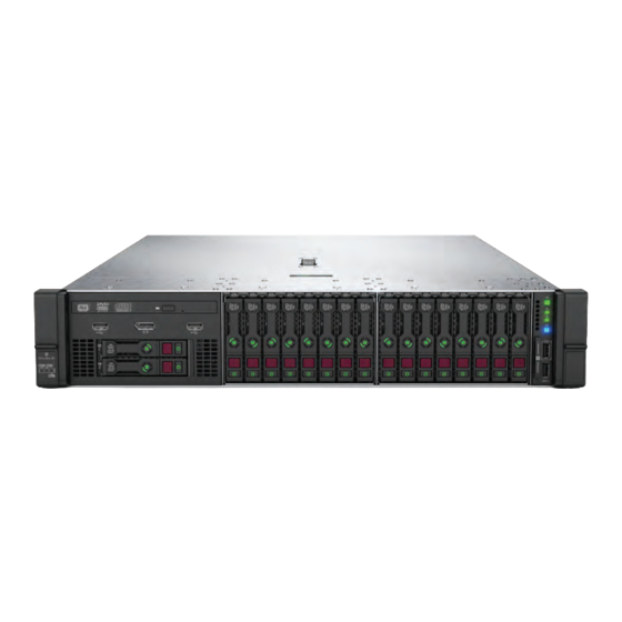
Page 8: Component Identification
Component identification Front panel components SFF front panel components Item Description Box 1 (optional drives or universal media bay) Box 2 (optional drives) Box 3 Drives 1-8 Serial label pull tab or optional Systems Insight Display iLO service port USB 3.0 port Universal media bay components Item Description... - Page 9 12-drive LFF front panel components Item Description Drive bays 8-drive LFF model front panel components Item Description Drives (optional) LFF power switch module Drive bays LFF power switch module components Component identification...
-
Page 10: Front Panel Leds And Buttons
Item Description Optical disk drive Serial label pull tab USB 3.0 port iLO service port Video display port Front panel LEDs and buttons SFF front panel LEDs and button Item Description Status Power On/Standby button and Solid green = System on system power LED* Flashing green (1 Hz/cycle per sec) = Performing power on sequence... - Page 11 Item Description Status NIC status LED* Solid green = Link to network Flashing green (1 Hz/cycle per sec) = Network active Off = No network activity UID button/LED* Solid blue = Activated Flashing blue: • 1 Hz/cycle per sec = Remote management or firmware upgrade in progress •...
- Page 12 Item Description Status Health LED* Solid green = Normal Flashing green (1 Hz/cycle per sec) = iLO is rebooting Flashing amber = System degraded Flashing red (1 Hz/cycle per sec) = System critical** Power On/Standby button and Solid green = System on system power LED* Flashing green (1 Hz/cycle per sec) = Performing power on sequence...
- Page 13 LFF power switch module LEDs and button Item Description Status UID button/LED* Solid blue = Activated Flashing blue: • 1 Hz/cycle per sec = Remote management or firmware upgrade in progress • 4 Hz/cycle per sec = iLO manual reboot sequence initiated •...
-
Page 14: Uid Button Functionality
**If the health LED indicates a degraded or critical state, review the system IML or use iLO to review the system health status. †Facility power is not present, power cord is not attached, no power supplies are installed, power supply failure has occurred, or the power button cable is disconnected. -
Page 15: Systems Insight Display Combined Led Descriptions
Description Status Processor LEDs Off = Normal Amber = Failed processor DIMM LEDs Off = Normal Amber = Failed DIMM or configuration issue Fan LEDs Off = Normal Amber = Failed fan or missing fan NIC LEDs Off = No link to network Solid green = Network link Flashing green = Network link with activity If power is off, the front panel LED is not active. - Page 16 Systems Insight Display Health System Status LED and color power LED Processor (amber) Amber One or more of the following conditions may exist: • Processor in socket X has failed. • Processor X is not installed in the socket. • Processor X is unsupported.
-
Page 17: Rear Panel Components
Systems Insight Display Health System Status LED and color power LED Power cap (off) — Amber Standby Power cap (green) — Flashing Waiting for power green Power cap (green) — Green Power is available. Power cap (flashing amber) — Amber Power is not available. -
Page 18: Rear Panel Leds
Rear panel LEDs Item Description Status UID LED Off = Deactivated Solid blue = Activated Flashing blue = System being managed remotely Link LED Off = No network link Green = Network link Activity LED Off = No network activity Solid green = Link to network Flashing green = Network activity Power supply... -
Page 19: System Board Components
System board components Item Description FlexibleLOM connector System maintenance switch Primary PCIe riser connector Front display port/USB 2.0 connector Table Continued System board components... -
Page 20: System Maintenance Switch Descriptions
Item Description x4 SATA port 1 x4 SATA port 2 x2 SATA port 3 x1 SATA port 4 Optical disk drive/SATA port 5 Front power/USB 3.0 connector Drive backplane power connectors Smart Storage Battery connector Chassis intrusion detection connector Drive backplane power connector Micro SD card slot Dual internal USB 3.0 ports Type-a Smart Array connector... -
Page 21: Processor, Heatsink, And Socket Components
Position Default Function — Reserved — Reserved — Reserved — Reserved — Reserved — Reserved You can access the redundant ROM by setting S1, S5, and S6 to On. When the system maintenance switch position 6 is set to the On position, the system is prepared to restore all configuration settings to their manufacturing defaults. -
Page 22: Sas/Sata Drive Components And Leds
SAS/SATA drive components and LEDs Item Description Status Locate • Solid blue = The drive is being identified by a host application. • Flashing blue = The drive carrier firmware is being updated or requires an update. Activity ring LED •... -
Page 23: Nvme Drive Components And Leds
NVMe drive components and LEDs Item Description Release lever Activity ring Do Not Remove LED Request to Remove NVMe Drive button Do not remove an NVMe SSD from the drive bay while the Do Not Remove button LED is flashing. The Do Not Remove button LED flashes to indicate the device is still in use. -
Page 24: Fan Bay Numbering
Item Description Status Do not remove LED • Off—OK to remove the drive. Removing the drive does not cause a logical drive to fail. • Solid white—Do not remove the drive. Removing the drive causes one or more of the logical drives to fail. -
Page 25: Drive Box Identification
Drive box identification Front boxes Item Description Box 1 Box 2 Box 3 Item Description Box 1 Box 2 Box 3 Rear boxes Item Description Box 4 Box 5 Box 6 Drive box identification... -
Page 26: Drive Bay Numbering
Item Description Box 4 Box 6 Midplane box (LFF only) Item Description Box 7 Drive bay numbering Drive bay numbering depends on how the drive backplanes are connected: • To a controller ◦ Embedded controllers use the onboard SATA ports. ◦... - Page 27 Component identification...
-
Page 28: Drive Bay Numbering: Sas Expander
Drive bay numbering: SAS expander Drive numbering through a SAS Expander is continuous. • SAS expander port 1 always connects to port 1 of the controller. • SAS expander port 2 always connects to port 2 of the controller. • SAS expander port 3 = drive numbers 1-4. - Page 29 When any stacked 2SFF drive cage is connected to the SAS expander, the drive numbering skips the second number to allow uFF drive bay numbering on page 31. For example, when a rear 2SFF drive cage is connected to SAS expander port 9, then the drive numbers are 25 and 27. When the front 24SFF bays are populated, any installed rear 2SFF drives are always 25 and 27.
-
Page 30: Drive Bay Numbering: Nvme Drives
Front 12LFF + Midplane 4LFF + All rear 2SFF: Drive bay numbering: NVMe drives If the server is populated with NVMe drives and NVMe risers: Drive bay numbering: NVMe drives... -
Page 31: Uff Drive Bay Numbering
uFF drive bay numbering There are two uFF drives in each drive carrier. If the drives are connected to a controller: • The left bay = The default bay number of the server • The right bay = The default bay number of the server + 100 If the drives are connected to a SAS expander: For example: •... -
Page 32: Operations
Operations Powering up the server To power up the server, press the Power On/Standby button. Power down the server Before powering down the server for any upgrade or maintenance procedures, perform a backup of critical server data and programs. IMPORTANT: When the server is in standby mode, auxiliary power is still being provided to the system. -
Page 33: Extending The Server From The Rack
3. After performing the installation or maintenance procedure, slide the server back into the rack, and then press the server firmly into the rack to secure it in place. WARNING: To reduce the risk of personal injury, be careful when pressing the server rail-release latches and sliding the server into the rack. -
Page 34: Removing The Server From The Rack
Removing the server from the rack To remove the server from a Hewlett Packard Enterprise, Compaq-branded, Telco, or third-party rack: Procedure 1. Power down the server. 2. Extend the server from the rack. 3. Disconnect the cabling and remove the server from the rack. For more information, see the documentation that ships with the rack mounting option. - Page 35 6. Secure the cables to the cable management arm. IMPORTANT: When using cable management arm components, be sure to leave enough slack in each of the cables to prevent damage to the cables when the server is extended from the rack. 7.
-
Page 36: Remove The Access Panel
Remove the access panel WARNING: To reduce the risk of personal injury from hot surfaces, allow the drives and the internal system components to cool before touching them. CAUTION: Do not operate the server for long periods with the access panel open or removed. Operating the server in this manner results in improper airflow and improper cooling that can lead to thermal damage. -
Page 37: Installing The Fan Cage
Installing the fan cage CAUTION: Do not operate the server for long periods with the access panel open or removed. Operating the server in this manner results in improper airflow and improper cooling that can lead to thermal damage. IMPORTANT: For optimum cooling, install fans in all primary fan locations. - Page 38 CAUTION: For proper cooling, do not operate the server without the access panel, baffles, expansion slot covers, or blanks installed. If the server supports hot-plug components, minimize the amount of time the access panel is open. Procedure 1. Power down the server. 2.
-
Page 39: Installing The Air Baffle
Installing the air baffle Procedure 1. Observe the following alerts. CAUTION: For proper cooling, do not operate the server without the access panel, baffles, expansion slot covers, or blanks installed. If the server supports hot-plug components, minimize the amount of time the access panel is open. -
Page 40: Removing A Riser Cage
Removing a riser cage CAUTION: To prevent damage to the server or expansion boards, power down the server and remove all AC power cords before removing or installing the PCI riser cage. Procedure 1. Power down the server. 2. Remove all power: a. -
Page 41: Removing A Riser Slot Blank
Removing a riser slot blank CAUTION: To prevent improper cooling and thermal damage, do not operate the server unless all PCI slots have either an expansion slot cover or an expansion board installed. Procedure 1. Power down the server. 2. Remove all power: a. -
Page 42: Releasing The Cable Management Arm
Releasing the cable management arm Release the cable management arm and then swing the arm away from the rack. Accessing the Systems Insight Display The Systems Insight Display is only supported on SFF models. To access a Systems Insight Display, use the following procedure. - Page 43 Operations...
-
Page 44: Setup
Setup HPE support services Delivered by experienced, certified engineers, HPE support services help you keep your servers up and running with support packages tailored specifically for systems. HPE support services let you integrate both hardware and software support into a single package. A number of service level options are available to meet your business and IT needs. -
Page 45: Temperature Requirements
• Leave a minimum clearance of 63.5 cm (25 in) in front of the rack. • Leave a minimum clearance of 76.2 cm (30 in) behind the rack. • Leave a minimum clearance of 121.9 cm (48 in) from the back of the rack to the back of another rack or row of racks. -
Page 46: Power Requirements
CAUTION: To reduce the risk of damage to the equipment when installing third-party options: • Do not permit optional equipment to impede airflow around the server or to increase the internal rack temperature beyond the maximum allowable limits. • Do not exceed the manufacturer’s TMRA. Power requirements Installation of this equipment must comply with local and regional electrical regulations governing the installation of information technology equipment by licensed electricians. -
Page 47: Rack Warnings
WARNING: To reduce the risk of personal injury from hot surfaces, allow the drives and the internal system components to cool before touching them. WARNING: To reduce the risk of personal injury, electric shock, or damage to the equipment, remove the power cord to remove power from the server. -
Page 48: Server Box Contents
• Avoid touching pins, leads, or circuitry. • Always be properly grounded when touching a static-sensitive component or assembly. Use one or more of the following methods when handling or installing electrostatic-sensitive parts: ◦ Use a wrist strap connected by a ground cord to a grounded workstation or computer chassis. Wrist straps are flexible straps with a minimum of 1 megohm ±10 percent resistance in the ground cords. -
Page 49: Registering The Server
• For the latest information on supported operating systems, see the Hewlett Packard Enterprise website. • The server does not ship with OS media. All system software and firmware is preloaded on the server. Registering the server To experience quicker service and more efficient support, register the product at the Hewlett Packard Enterprise Product Registration website. -
Page 50: Hardware Options Installation
Hardware options installation Product QuickSpecs For more information about product features, specifications, options, configurations, and compatibility, see the product QuickSpecs on the Hewlett Packard Enterprise website (http://www.hpe.com/info/qs). Introduction If more than one option is being installed, read the installation instructions for all the hardware options and identify similar steps to streamline the installation process. -
Page 51: Power Supply Options
Power supply options Hot-plug power supply calculations For hot-plug power supply specifications and calculators to determine electrical and heat loading for the server, see the Hewlett Packard Enterprise Power Advisor website. Installing a redundant hot-plug power supply CAUTION: All power supplies installed in the server must have the same output power capacity. Verify that all power supplies have the same part number and label color. -
Page 52: Drive Options
3. Insert the power supply into the power supply bay until it clicks into place. 4. Connect the power cord to the power supply. 5. Route the power cord. Use the cable management arm and best practices when routing cords and cables. 6. -
Page 53: Supported Drive Carriers
Do not remove an NVMe SSD from the drive bay while the Do Not Remove button LED is flashing. The Do Not Remove button LED flashes to indicate that the device is still in use. Removal of the NVMe SSD before the device has completed and ceased signal/traffic flow can cause loss of data. -
Page 54: Installing An Nvme Drive
4. Observe the LED status of the drive. Installing an NVMe drive CAUTION: To prevent improper cooling and thermal damage, do not operate the server unless all drive and device bays are populated with either a component or a blank. Procedure 1. -
Page 55: Installing A Uff Drive And Scm Drive Carrier
4. Observe the LED status of the drive. Installing a uFF drive and SCM drive carrier IMPORTANT: Not all drive bays support the drive carrier. To find supported bays, see the server QuickSpecs. Procedure 1. If needed, install the uFF drive into the drive carrier. 2. -
Page 56: Installing An M.2 Drive
4. Power on the server. To configure the drive, use HPE Smart Storage Administrator. Installing an M.2 drive This procedure is for replacing M.2 drives located on an expansion card, riser, or the system board only. Do not use this procedure to replace uFF drives. Prerequisites Before installing this option, be sure that you have the following: •... -
Page 57: Fan Options
The installation is complete. Fan options CAUTION: To avoid damage to server components, fan blanks must be installed in fan bays 1 and 2 in a single- processor configuration. CAUTION: To avoid damage to the equipment, do not operate the server for extended periods of time if the server does not have the optimal number of fans installed. -
Page 58: Installing High-Performance Fans
Installing high-performance fans CAUTION: Caution: To prevent damage server, ensure that all DIMM latches are closed and locked before installing the fans. CAUTION: Do not operate the server for long periods with the access panel open or removed. Operating the server in this manner results in improper airflow and improper cooling that can lead to thermal damage. -
Page 59: Memory Options
6. Install high-performance fans in all fan bays. 7. Install the air baffle. 8. Install the access panel. 9. Install the server into the rack. Memory options IMPORTANT: This server does not support mixing LRDIMMs and RDIMMs. Attempting to mix any combination of these DIMMs can cause the server to halt during BIOS initialization. -
Page 60: Hpe Smart Memory Speed Information
HPE Smart Memory speed information For more information about memory speed information, see the Hewlett Packard Enterprise website (https:// www.hpe.com/docs/memory-speed-table). DIMM label identification To determine DIMM characteristics, see the label attached to the DIMM. The information in this section helps you to use the label to locate specific information about the DIMM. -
Page 61: Installing A Dimm
Item Description Definition CAS latency P = CAS 15-15-15 T = CAS 17-17-17 U = CAS 20-18-18 V = CAS 19-19-19 (for RDIMM, LRDIMM) V = CAS 22-19-19 (for 3DS TSVLRDIMM) DIMM type R = RDIMM (registered) L = LRDIMM (load reduced) E = Unbuffered ECC (UDIMM) For more information about product features, specifications, options, configurations, and compatibility, see the product QuickSpecs on the Hewlett Packard Enterprise website (http://www.hpe.com/info/qs). -
Page 62: Controller Options
Install the access panel. Install the server in the rack. Connect each power cord to the server. 10. Connect each power cord to the power source. 11. Power up the server. Use the BIOS/Platform Configuration (RBSU) in the UEFI System Utilities to configure the memory mode. For more information about LEDs and troubleshooting failed DIMMs, see "Systems Insight Display combined LED descriptions."... -
Page 63: Installing A Universal Media Bay
3. Do one of the following: • Extend the server from the rack. • Remove the server from the rack. 4. Remove the access panel. 5. Do one of the following: • Remove the air baffle. • If installed, remove the 4LFF midplane drive cage. 6. - Page 64 Remove the bay blank. Route the USB and video cables through the opening. If installing a two-bay SFF front drive cage, install the drive cage. 10. Install the universal media bay. 11. (Optional) Install the optical disk drive. Hardware options installation...
-
Page 65: Drive Cage Options
12. Connect the cables. 13. Install the fan cage. 14. Install the air baffle. 15. Install the access panel. 16. Slide the server into the rack. 17. Connect each power cord to the server. 18. Connect each power cord to the power source. 19. - Page 66 CAUTION: To prevent damage to electrical components, properly ground the server before beginning any installation procedure. Improper grounding can cause ESD. Power down the server . Do one of the following: • Extend the server from the rack. • Remove the server from the rack . Remove the access panel.
-
Page 67: Installing A Front 6Sff Sas/Sata + 2Nvme Premium Drive Cage
11. Connect the data cables from the drive backplane to the NVMe riser. 12. Install drives or drive blanks. The installation is complete. Installing a front 6SFF SAS/SATA + 2NVMe Premium drive cage The drive cage can be installed in any box. This procedure covers installing the drive cage in box 1. Prerequisites A storage controller and high-performance fans are required when installing this drive cage. -
Page 68: Installing Airflow Labels
Connect the power cable. 10. Install a storage controller. 11. Connect the data cables from the drive backplane to the controller. 12. Install drives or drive blanks. The installation is complete. Installing airflow labels When an Express Bay drive cage is installed, airflow labels might be required: Prerequisites Before installing this option, be sure that you have the following: •... -
Page 69: Installing A Front 8Sff Sas/Sata Drive Cage In Box 1
◦ If the 2SFF drive cage is not installed, then install airflow labels as shown. ◦ If a 2SFF drive cage is installed, then install the airflow labels as shown. Installing a front 8SFF SAS/SATA drive cage in box 1 Prerequisites Before installing this option, be sure that you have the following: •... - Page 70 • Extend the server from the rack. • Remove the server from the rack . Remove the access panel. Remove the air baffle. Remove the fan cage. Remove the bay blank. Install the 8SFF front drive cage option. Connect the power and data cables. 10.
-
Page 71: Installing A Front 8Sff Sas/Sata Drive Cage In Box 2
Installing a front 8SFF SAS/SATA drive cage in box 2 Procedure Power down the server. Remove all power: a. Disconnect each power cord from the power source. b. Disconnect each power cord from the server. Do one of the following: •... -
Page 72: Installing A Front 2Sff Nvme/Sas/Sata Premium Drive Cage
10. Install the fan cage. 11. Install the access panel. 12. Slide the server into the rack. 13. Connect each power cord to the server. 14. Connect each power cord to the power source. 15. Power up the server. The installation is complete. Installing a front 2SFF NVMe/SAS/SATA Premium drive cage Prerequisites Before installing this option, be sure that you have the following:... - Page 73 Remove the SFF drive blank from the universal media bay. Install the drive cage into the universal media bay. Hardware options installation...
- Page 74 Install the optical disk drive tray. 10. Install the universal media bay. Hardware options installation...
-
Page 75: Installing A Midplane 4Lff Sas/Sata Drive Cage
11. Connect the power and data cables. 12. Install the access panel. 13. Slide the server into the rack. 14. Connect each power cord to the server. 15. Connect each power cord to the power source. 16. Power up the server. The installation is complete. - Page 76 Remove all riser cages. Connect the power cable to the drive backplane power connector on the system board. If connecting the data cable to the system board or a controller, connect the data cable. Prepare the drive cage for installation by lifting the latches on the drive cage. 10.
-
Page 77: Installing A Rear 2Sff Sas/Sata Drive Cage In The Primary Or Secondary Riser
11. Install drives or drive blanks. 12. Push down on the latches to lower the drive cage into place. 13. Connect the power and data cables to the drive backplane. The installation is complete. Installing a rear 2SFF SAS/SATA drive cage in the primary or secondary riser Prerequisites Before installing this option, be sure that you have the following: •... - Page 78 Procedure Power down the server. Remove all power: a. Disconnect each power cord from the power source. b. Disconnect each power cord from the server. Do one of the following: • Extend the server from the rack. • Remove the server from the rack . Remove the access panel.
-
Page 79: Installing A Rear 2Sff Sas/Sata Drive Cage Over The Power Supplies
Cable the drive backplane. Install drives or drive blanks. 10. Install the access panel. 11. Slide the server into the rack. 12. Connect each power cord to the server. 13. Connect each power cord to the power source. 14. Power up the server. The installation is complete. - Page 80 Remove the secondary wall blank. Remove the tertiary wall blank. Hardware options installation...
- Page 81 Install the drive cage compatible rear wall. Install the drive cage. Hardware options installation...
-
Page 82: Installing A Rear 3Lff Sas/Sata Drive Cage
Install drives or drive blanks. 10. Install the secondary rear wall or a riser cage. 11. Cable the drive backplane. 12. Install the access panel. 13. Slide the server into the rack. 14. Connect each power cord to the server. 15. - Page 83 Remove the rear wall blank. Install the three-bay LFF rear drive cage option. Hardware options installation...
-
Page 84: Riser And Riser Cage Options
Install drives or drive blanks. Connect the power and data cables. 10. Install the access panel. 11. Slide the server into the rack. 12. Connect each power cord to the server. 13. Connect each power cord to the power source. 14. -
Page 85: Installing Tertiary Risers
Install the riser. Install any expansion boards, if needed Connect data cables to the riser or expansion board, if needed. 10. Install the riser cage. 11. If needed, connect data cables to drive backlanes. The installation is complete. Installing tertiary risers Prerequisites Before installing this option, be sure that you have the following: •... -
Page 86: Installing A Secondary Riser Cage
• Disconnect each power cord from the power source. • Disconnect each power cord from the server. Do one of the following: • Extend the server from the rack. • Remove the server from the rack. Remove the access panel. Remove the riser cage. -
Page 87: Installing A Tertiary Riser Cage
• Extend the server from the rack. • Remove the server from the rack. 5. Remove the access panel. 6. Remove the rear wall blank. 7. Install any expansion boards, if needed. 8. Install the riser cage: The installation is complete. Installing a tertiary riser cage Prerequisites Before installing this option, be sure that you have the following:... - Page 88 Procedure 1. Observe the following alert. CAUTION: To prevent damage to the server or expansion boards, power down the server and remove all AC power cords before removing or installing the PCI riser cage. 2. Power down the server. 3. Remove all power: a.
-
Page 89: Installing The 2Nvme Slimsas Riser Option
8. Install any expansion boards, if needed 9. Install the tertiary riser cage: The installation is complete. Installing the 2NVMe slimSAS riser option Prerequisites Before installing this option, be sure that you have the following: • The components included with the hardware option kit •... -
Page 90: Installing The 8Nvme Slimsas Riser Option
• Disconnect each power cord from the power source. • Disconnect each power cord from the server. 3. Do one of the following: • Extend the server from the rack. • Remove the server from the rack. 4. Remove the access panel. 5. -
Page 91: Expansion Slots
To install the riser in the secondary position, install the secondary riser cage. 7. Connect data cables to the drive backplane. Expansion slots Supported PCIe form factors All slots support full-height expansion cards. Use the following information to find supported lengths for each slot. -
Page 92: Installing Expansion Boards
Primary riser connector PCIe slot and card 3-slot riser* 2-slot riser (Optional) 2-slot riser (Optional) length Slot 1 - Full-length/Full- PCIe3 x8 (8, 4, 2, 1) — PCIe3 x16 (16, 8, 4, 2, 1) height (FL/FH) Slot 2 - Half-length/Full- PCIe3 x16 (16, 8, 4, 2, 1) PCIe3 x16 (16, 8, 4, 2, 1) PCIe3 x16 (16, 8, 4, 2, 1) height (HL/FH) Slot 3 - Half-length/Full-... - Page 93 Procedure Power down the server. Remove all power: a. Disconnect each power cord from the power source. b. Disconnect each power cord from the server. Do one of the following: • Extend the server from the rack. • Remove the server from the rack . Remove the access panel.
-
Page 94: Installing A 12G Sas Expander Card
If internal cables are required for the expansion board, connect the cables. Install the riser cage. 10. Install the access panel. 11. Slide the server into the rack. 12. Connect each power cord to the server. 13. Connect each power cord to the power source. 14. - Page 95 • The components included with the hardware option kit • Storage cables for each drive box • A storage controller Procedure Power down the server. Remove all power: a. Disconnect each power cord from the power source. b. Disconnect each power cord from the server. Do one of the following: •...
-
Page 96: Installing A Gpu Card
13. Connect cables from the 12G SAS expander to the drive backplanes. A standard configuration is shown. For additional cabling diagrams, see "Cabling diagrams on page 118". 14. Install the fan cage. 15. Install the air baffle. 16. Install the access panel. 17. - Page 97 Prerequisites Before installing this option, be sure that you have the following: • The components included with the hardware option kit • T-30 Torx screwdriver • T-10 Torx screwdriver • High-performance heatsinks must be installed with this option. Procedure Observe the following alert. CAUTION: To prevent improper cooling and thermal damage, do not operate the server unless all PCIe slots have either an expansion slot cover or an expansion board installed.
- Page 98 Install high-performance heatsinks. 10. Install the air baffle. 11. Remove the rear wall blank. To install a tertiary GPU, remove the 12. Remove the PCIe blank. 13. Install the GPU into the riser. Hardware options installation...
- Page 99 14. Connect the power cable from the GPU to the riser. 15. Slide the retention clips to the unlocked position. 16. Install the riser cage. Hardware options installation...
-
Page 100: Installing An Intrusion Detection Switch
17. Slide the retention clips to the locked position. The installation is complete. Installing an intrusion detection switch Prerequisites Before installing this option, be sure that you have the following: • The components included with the hardware option kit Procedure 1. -
Page 101: Installing A Smart Storage Battery
• Extend the server from the rack. • Remove the server from the rack . 4. Remove the access panel. 5. Remove the air baffle. 6. Install the intrusion detection switch. Installing a Smart Storage Battery Prerequisites Before installing this option, be sure that you have the following: The components included with the hardware option kit Procedure Power down the server . -
Page 102: Installing A Rear Serial Port Interface
Install the cable. Install the fan cage. Install the air baffle. 10. Install the access panel. 11. Slide the server into the rack. 12. Connect each power cord to the server. 13. Connect each power cord to the power source. 14. - Page 103 Procedure Power down the server . Do one of the following: • Disconnect each power cord from the power source. • Disconnect each power cord from the server. Do one of the following: • Extend the server from the rack. •...
-
Page 104: Installing A Systems Insight Display
Install the serial port. Install the access panel. Install the server in the rack. Connect each power cord to the server. Connect each power cord to the power source. 10. Power up the server . The installation is complete. Installing a Systems Insight Display Prerequisites Before installing this option, be sure that you have the following: •... - Page 105 Procedure Power down the server. Remove all power: a. Disconnect each power cord from the power source. b. Disconnect each power cord from the server. Do one of the following: • Extend the server from the rack. • Remove the server from the rack . Remove the access panel.
-
Page 106: Installing A Flexiblelom Adapter
10. Connect the SID module cable to the front power/USB 3.0 connector. 11. Install the fan cage. 12. Install the air baffle. 13. Install the access panel. 14. Slide the server into the rack. 15. Connect each power cord to the server. 16. - Page 107 Install the FlexibleLOM adapter: Install the riser cage. Install the access panel. 10. Slide the server into the rack. 11. Connect the LAN segment cables. 12. Connect each power cord to the server. 13. Connect each power cord to the power source. 14.
-
Page 108: Installing A 1U Or High-Performance Heatsink
Installing a 1U or high-performance heatsink This procedure shows a standard heatsink as an example. The installation process is the same for all heatsinks. HPE recommends identifying the processor, heatsink, and socket components before performing this procedure. Prerequisites Before installing this option, be sure that you have the following: •... - Page 109 c. Lift the processor heatsink assembly and move it away from the system board. d. Turn the assembly over and place it on a work surface with the processor facing up. e. Install the dust cover. Separate the processor from the heatsink: a.
-
Page 110: Installing A Processor
11. Install the processor heatsink assembly. The installation is complete. Installing a processor Before performing this procedure, HPE recommends identifying the processor-heatsink module components. Prerequisites Before installing this option, be sure that you have the following: • The components included with the hardware option kit •... - Page 111 CAUTION: THE CONTACTS ARE VERY FRAGILE AND EASILY DAMAGED. To avoid damage to the socket or processor, do not touch the contacts. 2. Power down the server. 3. Remove all power: a. Disconnect each power cord from the power source. b.
-
Page 112: Hpe Trusted Platform Module 2.0 Option
The installation is complete. HPE Trusted Platform Module 2.0 Overview Use these instructions to install and enable an HPE TPM 2.0 Kit in a supported server. This option is not supported on Gen9 and earlier servers. This procedure includes three sections: 1. -
Page 113: Hpe Trusted Platform Module 2.0 Guidelines
IMPORTANT: In UEFI Boot Mode, the HPE TPM 2.0 Kit can be configured to operate as TPM 2.0 (default) or TPM 1.2 on a supported server. In Legacy Boot Mode, the configuration can be changed between TPM 1.2 and TPM 2.0, but only TPM 1.2 operation is supported. HPE Trusted Platform Module 2.0 Guidelines CAUTION: Always observe the guidelines in this document. - Page 114 WARNING: To reduce the risk of personal injury, electric shock, or damage to the equipment, remove power from the server by removing the power cord. The front panel Power On/Standby button does not shut off system power. Portions of the power supply and some internal circuitry remain active until AC power is removed.
- Page 115 3. Install the TPM cover: a. Line up the tabs on the cover with the openings on either side of the TPM connector. b. To snap the cover into place, firmly press straight down on the middle of the cover. 4.
-
Page 116: Enabling The Trusted Platform Module
Enabling the Trusted Platform Module When enabling the Trusted Platform module, observe the following guidelines: • By default, the Trusted Platform Module is enabled as TPM 2.0 when the server is powered on after installing it. • In UEFI Boot Mode, the Trusted Platform Module can be configured to operate as TPM 2.0 or TPM 1.2. •... -
Page 117: Retaining The Recovery Key/Password
The server reboots a second time without user input. During this reboot, the TPM setting becomes effective. 8. Enable TPM functionality in the OS, such as Microsoft Windows BitLocker or measured boot. For more information, see the Microsoft website. Retaining the recovery key/password The recovery key/password is generated during BitLocker setup, and can be saved and printed after BitLocker is enabled. -
Page 118: Cabling
Cabling Servers Storage Cabling Guidelines When installing cables, observe the following: • All ports are labeled: ◦ System board ports ◦ Controller ports ◦ 12G SAS Expander ports • Most data cables have labels near each connector with destination port information. •... - Page 119 Option kit Cable part From Power cable part number* number Rear 2SFF SAS/SATA riser drive 869823-001 Drive 869806-001 System board cage backplane SAS Expander Controller Rear 3LFF SAS/SATA drive cage 869823-001 Drive 869810-001 System board backplane SAS Expander Controller 12G SAS Expander card SAS Expander Controller 869802-001 869803-001...
-
Page 120: Cable Routing: Front 2Sff Drive Option For Sff
Option kit Cable part From Power cable part number number 2-Port Slim SAS Riser, Tertiary PCIe riser Backplane 869812-001 PCIe 869812-001 4-Port Slim SAS Riser PCIe riser Backplane 869811-001 776402-001 1-Port Slim SAS Riser 869812-001 PCIe riser Backplane NVMe Direct Attach Kit (875092-001) NVMe SFF Riser Kit (875091-001) Power cables kit (875096-001) Table 3: GPU power... -
Page 121: Cable Routing: Front 2Sff Drive Option For Lff
Option 2: SAS Expander Option 3 (not shown): A controller Cable routing: Front 2SFF drive option for LFF Option 1: System board Cable routing: Front 2SFF drive option for LFF... -
Page 122: Cable Routing: Front 2Sff Drive Options (3 Position Cable)
Option 2: Controller Option 3 (not shown): SAS Expander Cable routing: Front 2SFF drive options (3 position cable) SFF models Cable routing: Front 2SFF drive options (3 position cable) -
Page 123: Cable Routing: Front 8Sff Drive Options
LFF models Cable routing: Front 8SFF drive options Box 1 to SAS Expander Cable routing: Front 8SFF drive options... - Page 124 Box 2 to SAS Expander All boxes Cabling...
-
Page 125: Cable Routing: Front 8Sff Nvme/Sas Premium Drive Option
Cable routing: Front 8SFF NVMe/SAS premium drive option The backplane shown is in box 3. Cable routing: Front 8SFF NVMe drive options Box 1 Cable routing: Front 8SFF NVMe/SAS premium drive option... - Page 126 Box 2 Box 3 Cabling...
-
Page 127: Cable Routing: Front 2Sff Nvme Drive Option For Sff
Cable routing: Front 2SFF NVMe drive option for SFF Cable routing: Front 2SFF NVMe drive option for SFF... -
Page 128: Cable Routing: Front 2Sff Nvme Drive Option For Lff
Cable routing: Front 2SFF NVMe drive option for LFF Cable routing: Midplane 4LFF drive option Cable routing: Front 2SFF NVMe drive option for LFF... -
Page 129: Cable Routing: Rear 3Lff Drive Option
Cable routing: Rear 3LFF drive option Cable routing: Rear 2SFF drive options Rear 2SFF drive option to a SAS expander, both in the primary slot Rear 2SFF drive option in the secondary slot to a SAS Expander in primary slot Rear 2SFF drive option above the power supplies to a controller Cable routing: Rear 3LFF drive option... -
Page 130: Cable Routing: Hpe 12G Sas Expander To A Controller
Cable routing: HPE 12G SAS Expander to a controller Observe the following: • Port 1 always connects to port 1 of the controller. • Port 2 always connects to port 2 of the controller. SAS expander to an a-type controller SAS expander to a p-type controller Cable routing: HPE 12G SAS Expander to a controller... -
Page 131: Cable Routing: Systems Insight Display
Cable routing: Systems Insight Display An SFF model is shown. The routing is the same for LFF. Cable routing: Systems Insight Display... -
Page 132: Software And Configuration Utilities
Software and configuration utilities Server mode The software and configuration utilities presented in this section operate in online mode, offline mode, or in both modes. Software or configuration utility Server mode Active Health System on page 132 Online and Offline HPE iLO 5 on page 133 Online and Offline HPE Smart Storage Administrator on page 138... -
Page 133: Active Health System Data Collection
• Consolidated health and service alerts with precise time stamps • Agentless monitoring that does not affect application performance For more information about the Active Health System, see the iLO user guide on the Hewlett Packard Enterprise website. Active Health System data collection The Active Health System does not collect information about your operations, finances, customers, employees, or partners. -
Page 134: Ilo Service Port
iLO 5 supports the following features: • Group health status—View server health and model information. • Group Virtual Media—Connect scripted media for access by the servers in an iLO Federation group. • Group power control—Manage the power status of the servers in an iLO Federation group. •... -
Page 135: Ilo Amplifier Pack
For more information, see the following website: http://www.hpe.com/info/resttool. iLO Amplifier Pack The iLO Amplifier Pack is an advanced server inventory and firmware and driver update solution that enables rapid discovery, detailed inventory reporting, and firmware and driver updates by leveraging iLO advanced functionality. -
Page 136: Management Security
• SUSE Linux Enterprise Server • VMware ESXi/vSphere Custom Image Not all versions of an OS are supported. For information about specific versions of a supported operating system, see the OS Support Matrix on the Hewlett Packard Enterprise website (http://www.hpe.com/info/ ossupport). -
Page 137: Selecting The Boot Mode
Selecting the boot mode This server provides two Boot Mode configurations: UEFI Mode and Legacy BIOS Mode. Certain boot options require that you select a specific boot mode. By default, the boot mode is set to UEFI Mode. The system must boot in UEFI Mode to use certain options, including: •... -
Page 138: Launching The Embedded Uefi Shell
• Using the System Utilities options described in the following sections. • Using the RESTful API to clear and restore certificates. For more information, see the Hewlett Packard Enterprise website (www.hpe.com/support/restfulinterface/docs). • Using the secboot command in the Embedded UEFI Shell to display Secure Boot databases, keys, and security reports. -
Page 139: Usb Support
For more information, see HPE Smart Array SR Configuration Guide at the Hewlett Packard Enterprise website. USB support Hewlett Packard Enterprise servers support all USB operating speeds depending on the device that is connected to the server. External USB functionality Hewlett Packard Enterprise provides external USB support to enable local connection of USB devices for server administration, configuration, and diagnostic procedures. - Page 140 SUM overview SUM is a tool for firmware and driver maintenance on servers, BladeSystem enclosures, Moonshot systems, and other nodes. It provides a browser-based GUI or a command-line scripting interface for flexibility and adaptability. SUM identifies associated nodes you can update at the same time to avoid interdependency issues. Key features of SUM include: •...
-
Page 141: Updating Firmware From The System Utilities
NOTE: Do not manage one node with iLO Amplifier Pack and HPE OneView. Updating firmware from the System Utilities Use the Firmware Updates option to update firmware components in the system, including the system BIOS, NICs, and storage cards. Procedure 1. -
Page 142: Drivers
Drivers IMPORTANT: Always perform a backup before installing or updating device drivers. The server includes new hardware that may not have driver support on all OS installation media. If you are installing an Intelligent Provisioning-supported OS, use Intelligent Provisioning on page 135 and its Configure and Install feature to install the OS and latest supported drivers. -
Page 143: Change Control And Proactive Notification
Change control and proactive notification Hewlett Packard Enterprise offers Change Control and Proactive Notification to notify customers 30 to 60 days in advance of the following: • Upcoming hardware and software changes • Bulletins • Patches Let us know what Hewlett Packard Enterprise commercial products you own and we will send you the latest updates to keep your business running smoothly. -
Page 144: Troubleshooting
Troubleshooting NMI functionality An NMI crash dump enables administrators to create crash dump files when a system is hung and not responding to traditional debugging methods. An analysis of the crash dump log is an essential part of diagnosing reliability problems, such as hanging operating systems, device drivers, and applications. -
Page 145: Safety, Warranty, And Regulatory Information
Safety, warranty, and regulatory information Safety and regulatory compliance For important safety, environmental, and regulatory information, see Safety and Compliance Information for Server, Storage, Power, Networking, and Rack Products, available at the Hewlett Packard Enterprise website. Warranty information Servers and Options HPE Enterprise Servers HPE Storage Products HPE Networking Products... -
Page 146: Turkey Rohs Material Content Declaration
• Belarus: • Kazakhstan: Manufacturing date: The manufacturing date is defined by the serial number. CCSYWWZZZZ (serial number format for this product) Valid date formats include: • YWW, where Y indicates the year counting from within each new decade, with 2000 as the starting point; for example, 238: 2 for 2002 and 38 for the week of September 9. -
Page 147: Specifications
Specifications Environmental specifications Specification Value Temperature range — Operating 10°C to 35°C (50°F to 95°F) Nonoperating -30°C to 60°C (-22°F to 140°F) Relative humidity (noncondensing) — Operating Minimum to be the higher (more moisture) of -12°C (10.4°F) dew point or 8% relative humidity Maximum to be 24°C (75.2°F) dew point or 90% relative humidity Nonoperating... -
Page 148: Power Supply Specifications
• SFF drive (1) • Drive blanks (7) • Drive bay blanks for bays 1 and 2 (2) • Fan assemblies (4) • Fan blanks (2) • Standard heatsink (1) • 1P air baffle (1) • X8 HPE Flexible Smart Array Controller (1) •... -
Page 149: Hpe 800W Flex Slot Platinum Hot-Plug Power Supply
Rated input frequency 50 Hz to 60 Hz Not applicable to 240 VDC Rated input current 5.8 A at 100 VAC 2.8 A at 200 VAC 2.4 A at 240 VDC for China only Maximum rated input power 580 W at 100 VAC 560 W at 200 VAC 576 W at 240 VDC for China only... -
Page 150: Hpe 800W Flex Slot Titanium Plus Hot-Plug Power Supply
Rated input current 9.4 A at 100 VAC 4.5 A at 200 VAC 3.8 A at 240 VDC for China only Maximum rated input power 940 W at 100 VAC 900 W at 200 VAC 912 W at 240 VDC for China only BTUs per hour 3207 at 100 VAC... -
Page 151: Hpe 800W Flex Slot Universal Hot-Plug Power Supply
Maximum rated input power 870 W at 200 VAC 870 W at 240 VAC 870 W at 240 VDC for China only BTUs per hour 2969 at 200 VAC 2969 at 240 VAC 2969 at 240 VDC for China only Power supply output Rated steady-state power 800 W at 200 VAC to 240 VAC... -
Page 152: Hpe 800W Flex Slot -48Vdc Hot-Plug Power Supply
Rated steady-state power 800 W at 200 VAC to 277 VAC input 800 W at 380 VDC input Maximum peak power 800 W at 200 VAC to 277 VAC input 800 W at 380 VDC input HPE 800W Flex Slot -48VDC Hot-plug Power Supply Specification Value Input requirements... -
Page 153: Hpe 1600W Flex Slot Platinum Hot Plug Power Supply
CAUTION: This equipment is designed to permit the connection of the earthed conductor of the DC supply circuit to the earthing conductor at the equipment. If this connection is made, all of the following must be met: • This equipment must be connected directly to the DC supply system earthing electrode conductor or to a bonding jumper from an earthing terminal bar or bus to which the DC supply system earthing electrode conductor is connected. -
Page 154: Support And Other Resources
Support and other resources Accessing Hewlett Packard Enterprise Support • For live assistance, go to the Contact Hewlett Packard Enterprise Worldwide website: http://www.hpe.com/assistance • To access documentation and support services, go to the Hewlett Packard Enterprise Support Center website: http://www.hpe.com/support/hpesc Information to collect •... -
Page 155: Remote Support
Some parts do not qualify for CSR. Your Hewlett Packard Enterprise authorized service provider will determine whether a repair can be accomplished by CSR. For more information about CSR, contact your local service provider or go to the CSR website: http://www.hpe.com/support/selfrepair Remote support Remote support is available with supported devices as part of your warranty or contractual support... -
Page 156: Regulatory Information
Regulatory information To view the regulatory information for your product, view the Safety and Compliance Information for Server, Storage, Power, Networking, and Rack Products, available at the Hewlett Packard Enterprise Support Center: www.hpe.com/support/Safety-Compliance-EnterpriseProducts Additional regulatory information Hewlett Packard Enterprise is committed to providing our customers with information about the chemical substances in our products as needed to comply with legal requirements such as REACH (Regulation EC No 1907/2006 of the European Parliament and the Council). - Page 157 Documentation feedback Hewlett Packard Enterprise is committed to providing documentation that meets your needs. To help us improve the documentation, send any errors, suggestions, or comments to Documentation Feedback. When submitting your feedback, include the document title, part number, edition, and publication date located on the front cover of the document.
Need help?
Do you have a question about the BCD221 and is the answer not in the manual?
Questions and answers