Table of Contents
Advertisement
Quick Links
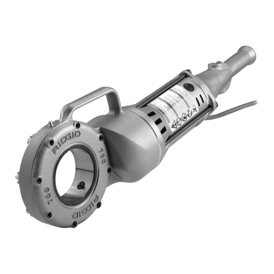
700
EN
P.
FR
P.
ES
P.
DE
P.
NL
P.
IT
P.
PT
P.
SV
P. 107
DA
P. 121
NO
P. 135
FI
P. 149
PL
P. 163
CZ
P. 179
SK
P. 195
RO
P. 209
HU
P. 225
EL
P. 241
HR
P. 257
SL
P. 271
SR
P. 285
RU
P. 299
TR
P. 315
KK
P. 329
Find Quality Products Online at:
1
13
27
43
59
75
91
GlobalTestSupply
www.
Tools For The Professional
RIDGE TOOL COMPANY
.com
TM
sales@GlobalTestSupply.com
Advertisement
Table of Contents

Summary of Contents for Ridge 700 Power drive
-
Page 1: Ridge Tool Company
P. 135 P. 149 P. 163 P. 179 P. 195 P. 209 P. 225 P. 241 P. 257 P. 271 P. 285 P. 299 P. 315 RIDGE TOOL COMPANY P. 329 GlobalTestSupply www. .com Find Quality Products Online at: sales@GlobalTestSupply.com... -
Page 2: Table Of Contents
Set-Up and Operation ..................................6 Installing Die Heads ..................................6 Resisting Threading Forces ................................7 Threading ......................................8 Inspecting Threads..................................9 700 Power Drive – Other Uses ................................9 Maintenance Instructions Cleaning ......................................10 Lubrication ....................................10 Changing Dies in 12-R Die Heads ..............................10 Replacing Brushes in Motor ................................10 Optional Equipment ..................................11... -
Page 3: Recording Form For Machine Serial Number
Failure to understand and follow the contents of 700 Power Drive this manual may result in Record Serial Number below and retain product serial number which is located on name plate. electrical shock, fire and/or serious personal injury. -
Page 4: Safety Symbols
700 Power Drive Safety Symbols In this operator’s manual and on the product, safety symbols and signal words are used to communicate important safe- ty information. This section is provided to improve understanding of these signal words and symbols. This is the safety alert symbol. It is used to alert you to potential personal injury hazards. Obey all safety messages that follow this symbol to avoid possible injury or death. -
Page 5: Personal Safety
Read these precautions carefully before using the • If devices are provided for the connection of dust 700 Power drive to reduce the risk of electrical extraction and collection facilities, ensure these are shock,striking, crushing or other serious injury. -
Page 6: Description, Specifications And Standard Equipment Description
The RIDGID ® Model 700 Power Drive is designed to pro- risk of injury. vide power for threading pipe and conduit. Forward and Reverse rotation can be selected with a reversible switch. -
Page 7: Standard Equipment
Standard equipment support device, including the handles and controls. This aids inspection and helps prevent the machine The Model 700 Power Drive comes with the following or control from slipping from your grip. items: 3. Inspect the power drive for the following: •... -
Page 8: Set-Up And Operation
8. Release the switch button and with dry hands unplug cord. the machine. 2. Inspect the pipe to be threaded and associated fittings and confirm that the 700 Power Drive is a correct tool Set-up and operation for the job. See Specifications. WARNING 3. -
Page 9: Resisting Threading Forces
1. Securely install the torque arm into the fan housing of Using the No. 775 Support Arm: the 700 Power Drive. A 5" (127 mm) long piece of ½" schedule 80 steel pipe with a ½" NPT thread can also 1. -
Page 10: Threading
700 Power Drive Other Support Methods: palm of free hand to start the thread (Figure 8). Do not wear gloves, jewelry or use a rag while pushing on the Place the power drive motor housing (see Figure 1) a gainst cover plate –... -
Page 11: Inspecting Threads
If there is any doubt about the use 2. Visually inspect thread. Threads should be smooth of the 700 Power Drive for these other purposes, do not and complete, with good form. If issues such as use it. -
Page 12: Maintenance Instructions
5. Tighten the four screws securely. Remove the thread- Do not overload the equipment. ed pipe and make a test cut. • Use such that the 700 Power Drive reaction force Screws pulls away from the user. Cover •... -
Page 13: Optional Equipment
To reduce the risk of serious injury, only use equip- RIDGID Thread Cutting Oils, including Hazard Identi fi ca tion, ment specifically designed and recommended for use with the 700 Power drive such as those listed First Aid, Fire Fighting, Accidental Release Measures, below. -
Page 14: Troubleshooting
700 Power Drive Troubleshooting PRoBLeM PoSSIBLe ReASoNS SoLuTIoN Machine will not run. Brushes do not touch armature. Check brushes, replace if worn. Dull dies. Replace dies. Machine not able to thread. Overload due to torn or out-of-round threads. See possible reasons below.
Need help?
Do you have a question about the 700 Power drive and is the answer not in the manual?
Questions and answers