
Summary of Contents for Cellocator CelloTrack T
-
Page 1: Installation Guide
CelloTrack T Installation Guide Proprietary and Confidential Version 1.2 Revised and Updated: July 8, 2014 Copyright © 2014 by Pointer Telocation, Ltd. -
Page 2: Legal Notices
CelloTrack T Installation Guide Legal Notices IMPORTANT 1. All legal terms and safety and operating instructions should be read thoroughly before the product accompanying this document is installed and operated. 2. This document should be retained for future reference. 3. Attachments, accessories or peripheral devices not supplied or recommended in writing by Pointer Telocation Ltd. - Page 3 CelloTrack T Installation Guide Intellectual Property Copyright in and to this document is owned solely by Pointer Telocation Ltd. Nothing in this document shall be construed as granting you any license to any intellectual property rights subsisting in or related to the subject matter of this document including, without limitation, patents, patent applications, trademarks, copyrights or other intellectual property rights, all of which remain the sole property of Pointer Telocation Ltd.
-
Page 4: Table Of Contents
CelloTrack T Installation Guide Table of Contents Introduction ......................5 Overview........................5 Abbreviations ......................5 References ........................5 Revision History ......................5 CelloTrack Interfaces ....................6 The CelloTrack Interface ....................7 The CelloTrack Power Interface ..................8 CelloTrack Connector ....................9 CelloTrack Power Harness .................... -
Page 5: Introduction
CelloTrack T Installation Guide Introduction Overview This guide provides the necessary information for technicians to install the CelloTrack T unit, and the CelloTrack Power unit. It describes how to install and verify the proper functioning of the kit elements. Abbreviations... - Page 6 CelloTrack T Installation Guide Version Date Description reference 08/07/2014 Correct LEDs names in The CelloTrack Interface section. Modify the Charging the Unit Battery section CelloTrack T Installation Guide Page 6 of 20 Copyright © 2014 by Pointer Telocation, Ltd.
-
Page 7: Cellotrack Interfaces
CelloTrack T Installation Guide CelloTrack Interfaces The CelloTrack Interface 1 – FB (Front Button) 2 – GSM LED 3 – SYS LED 4 – Cradle Tamper Switch 5 – Cradle 6 – Unit Tamper Switch 7 – Connector 8 – Connector Cover 9 –... -
Page 8: The Cellotrack Power Interface
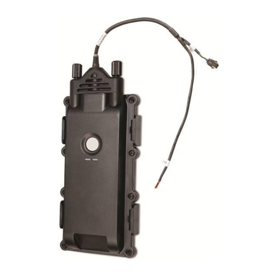
CelloTrack T Installation Guide The CelloTrack Power Interface 1. CelloTrack Power harness (pigtail) 2. FB (Front Button) 3. GSM LED 4. SYS LED CelloTrack T Installation Guide Page 8 of 20 Copyright © 2014 by Pointer Telocation, Ltd. -
Page 9: Cellotrack Connector
CelloTrack T Installation Guide CelloTrack Connector The CelloTrack 6-pin connector is protected by a plastic cover, providing IP67 compliance. The following illustration shows the CelloTrack unit with the rubber cover removed. Pin 6 Pin 1 The connector pin out is as follows: Pin 1 –... -
Page 10: Cellotrack Power Harness
CelloTrack T Installation Guide CelloTrack Power Harness The CelloTrack Power utilizes a 60-cm pigtail harness which ends with several free wires and a connector for the programming cable, as described in the following table. Color Function Free Wire Programming Connector Pin No. -
Page 11: Installation Instructions
------------------------------------------------------------------------------------------------ Perform the following steps when installing CelloTrack T devices: 1. Verify that you have all necessary parts for your installation. 2. Setup the CelloTrack (see Initial Setup for the CelloTrack and Initial Setup for the CelloTrack Power ). -
Page 12: Initial Setup For The Cellotrack
CelloTrack T Installation Guide Set Of Star Keys Set Of Allen Keys Regular Pliers Needle-Nose Pliers Initial Setup for the CelloTrack To setup the CelloTrack unit, perform the following steps: ------------------------------------------------------------------------------------------------ NOTE: The unit set up should be conducted under lab conditions. -
Page 13: Initial Setup For The Cellotrack Power
CelloTrack T Installation Guide 3. Connect the charger to the CelloTrack connector. If the battery is not fully charged the charger LED color is red. 4. Wait till the LED on the charger changes its color from red to green. -
Page 14: Mounting The Cellotrack Device
CelloTrack T Installation Guide Screw and plastic bar which hold the cradle tamper switch in its non-active position Mounting the CelloTrack Device Perform the following steps in order to mount the CelloTrack 3G device correctly: 1. Remove the CelloTrack device from the cradle. -
Page 15: Mounting With The Magnetic Cradle
CelloTrack T Installation Guide Mounting with the Magnetic Cradle Perform the following steps in order to mount the CelloTrack with the magnetic cradle correctly: 1. Choose a metal surface on the vehicle’s body that has high iron content and make sure that it is as clean as possible. -
Page 16: Wiring Guidelines For The Cellotrack Power
CelloTrack T Installation Guide Wiring Guidelines for the CelloTrack Power 3.8.1 Connecting Wires hod when connecting wires, such as connecting It is recommended to use the following met CelloTrack Power to Constant or to PTO/Ignition (refer to the full wiring diagrams in the following sections): Split the wire, insert a fuse holder wire through, and twist around. -
Page 17: Cellotrack Power Wiring Connection: Digital Input Not In Use
CelloTrack T Installation Guide CelloTrack Power Wiring Connection: Digital Input not in Use Orange and Brown wires not connected 3.10 CelloTrack Power Wiring Connection: Digital Input Connected to Ignition Orange Brown CelloTrack T Installation Guide Page 17 of 20 Copyright © 2014 by Pointer Telocation, Ltd. -
Page 18: Cellotrack Power Wiring Connection: Wiring To Pto
CelloTrack T Installation Guide 3.11 CelloTrack Power Wiring Connection: Wiring to PTO Orange or Brown wire CelloTrack T Installation Guide Page 18 of 20 Copyright © 2014 by Pointer Telocation, Ltd. -
Page 19: Cellotrack Activation And Deactivation
CelloTrack T Installation Guide 3.12 CelloTrack Activation and Deactivation 3.12.1 Activation 1. After mounting and properly placing your CelloTrack device in the cradle, you may switch your unit on to begin tracking. 2. Make sure the unit is correctly and securely mounted on the cradle and the Tamper Switch is pressed. - Page 20 CelloTrack T Installation Guide 3.12.3 Panic Alert While the unit is active, press the Front Button. The “Panic button triggered” procedure is initiated. 3.12.4 Tamper Detection and Alert Removing an activated unit from the cradle generates a tamper detection event that will be sent immediately to the server.