
Related Manuals for CLIMAVENETA i-LIFE SLIM 102

Summary of Contents for CLIMAVENETA i-LIFE SLIM 102
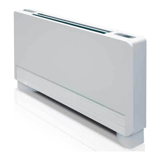
- Page 1 INSTALLATION - USER - MAINTENANCE MANUAL Fan coil with casing or for built-in installation, with tangential fan and inverter controlled brushless motor i-LIFE SLIM 102÷502...
-
Page 2: Table Of Contents
U I A U I A CONTENTS General warnings Water connections Fundamental safety rules Condensate drain U I A Product range Filling the system Rated technical specifications Venting air when filling the system Overall dimensions Electrical connections Packaging Maintenance Storage on site Cleaning the outside of the unit Installation - Positioning the unit Cleaning the air intake filter... -
Page 3: U I A General Warnings
U I A GENERAL WARNINGS After having removed the packing, check that the con- If the appliance is not used for a long period, proceed as tents are intact and complete. follows: In the event of discrepancies, contact the service centre - Move the main system switch to the “off”... -
Page 4: Product Range
U I A PRODUCT RANGE The i-LIFE SLIM range of fan coils comprises 4 versions, i-LIFE SLIM DLIU DLIU, DLMV, DLMO and DLRV, each of which available in built-in fan coil without panelling (suitable for built-in horizon- five sizes, with different performance and overall dimen- tal or vertical installations) sions. -
Page 5: Packaging
OVERALL DIMENSIONS i-LIFE SLIM DLIU built-in fan coil Dimensions 1125 1325 63,5 PACKAGING The units are delivered in standard packaging comprising a Inside the unit is an envelope containing the user, installa- cardboard box on pallets; the accessories are supplied sep- tion and maintenance manual. -
Page 6: Installation - Positioning The Unit
INSTALLATION - POSITIONING THE UNIT Avoid installing the unit: - the wall where the unit is installed is perfectly flat; - in places exposed to direct sunlight; - there is sufficient clearance around the unit to allow - near sources of heat; proper air circulation at the intake and outlet;... -
Page 7: Dismantling/Assembling The Casing
DISMANTLING / ASSEMBLING THE CASING - Remove the front grill. - Remove the filter, pulling it outwards horizontally - Unscrew the fastening screws. - Lift the casing in one piece, as shown in the figure. VERTICAL INSTALLATION For floor-standing assembly using the mouldings, see the Then secure the two brackets in place by completely tight- individual instruction sheets and the corresponding manual ening the four screws. -
Page 8: Horizontal Installation
HORIZONTAL INSTALLATION Use the paper template, and trace the position of the two fas- For installation of DLMO versions, the horizontal condensate tening brackets and the two rear screws on the ceiling. collection pan kits are available as accessories. Drill the holes with a suitable drill bit and insert the anchors (2 DLRV versions must not be installed horizontally. -
Page 9: Front Grill Safety Support Assembly
FRONT GRILL SAFETY SUPPORT ASSEMBLY (HORIZONTAL VERSIONS) If the fan coil is installed in the horizontal position, to ensure These supports are designed to stop the grill from falling. safety when cleaning/replacing the filters, the installer must - Separate the two clamps; fit the two safety clamps provided in the bag supplied - open the front grill and completely unscrew the spring together with the instruction booklet and the accessories. -
Page 10: Water Connections
WATER CONNECTIONS Dimensions Pipe diameter The choice and sizing of the water lines is the responsibility The water lines and the joints must be thermally insulated. of the designer, who must apply best working practice and comply with the legislation in force, also considering that Make sure the pipes are completely insulated. -
Page 11: Filling The System
CONDENSATE DRAIN Assembling the condensate drain pipe on horizontal for the correct condensate drain. (see fig. 1) versions To assemble the horizontal drain pan on DLMO versions, N.B. warnings for horizontal installation: see the instructions supplied with the horizontal pan kit. - make sure that the unit is perfectly level, or with a slight - make sure that the “L”... -
Page 12: Electrical Connections
ELECTRICAL CONNECTIONS Make the electrical connections following the instructions The appliance must be connected to the power supply via a shown under General warnings and Fundamental safety disconnect switch with minimum contact opening of 3 mm, rules, with reference to the diagrams provided in the acces- i.e. - Page 13 CLEANING THE AIR INTAKE FILTER Cleaning the filtering media Never use the appliance without the mesh filter. - use a vacuum cleaner to remove the dust from the filter with The appliance is fitted with a safety switch that prevents - wash the filter under running water, without using deter- the fan from operating if the panel is not fitted or is posi- gents or solvents, and leave it to dry.
-
Page 14: Tips On Saving Energy
TIPS ON SAVING ENERGY - Keep the filters clean at all times; - where possible, in cooling operation limit exposure of the - where possible, keep the doors and windows in the air- air-conditioned room to direct sunlight (use curtains, shut- conditioned room closed;...
Need help?
Do you have a question about the i-LIFE SLIM 102 and is the answer not in the manual?
Questions and answers