
Summary of Contents for Aitelong SAT-17T
- Page 1 Instruction Manual SAT-17T OPTICAL FUSION SPLICER Before operating the equipment, please carefully read this instruction manual Do follow all safety instructions and warnings covered in this manual. Take the manual for safe keeping...
- Page 2 Thanks for choose Aitelong! The information contained in this document is subject to change without notice. All rights reserved. Reproduction, adaptation, or translation of this material is prohibited without prior written permission of Guanggu Inc., except as allowed under copyright laws.
-
Page 3: Table Of Contents
SAT-17T Fusion Splicer Instruction Manual Contents WARNINGS & CAUTIONS ............1 PRODUCT INTRODUCTION ............. 6 1. Introduction ..............6 2. Features ................6 3. Technical Specifications ........... 7 4. Description and Function of Splicer ........10 PANEL AND INTERFACE INSTRUCTIONS ......13 ... - Page 4 SAT-17T Fusion Splicer Instruction Manual APPENDIX 1 WARNING INFO. LIST ........42 APPENDIX 2 ERROR MESSAGE LIST ........47 APPENDIX 3 GUARANTY ............49 ...
-
Page 5: Warnings & Cautions
SAT-17T Fusion Splicer Instruction Manual Warnings & Cautions This machine is specially designed for splicing optical fibers. Any misuse of this equipment for other applications, like splicing anything not optical fiber, will seriously damage the machine. Manufacturer take much consideration to user’s personal safety and injury, and provided a lot of Safety &... - Page 6 SAT-17T Fusion Splicer Instruction Manual Warnings If any following condition happens, please disconnect the AC power cord from the AC adapter inlet or the wall socket and hold power button to force power off immediately to ensure the equipment safety, and contact with maintenance center.
- Page 7 SAT-17T Fusion Splicer Instruction Manual splicer off and disconnect the AC power cord before replacing the electrodes. Safety goggle should always be worn during optical fiber preparation and splicing operation. Optical fiber fragments can be extremely dangerous if it comes into contact with the eye, skin, or has been ingested.
- Page 8 SAT-17T Fusion Splicer Instruction Manual battery and make sure the liquid does not contact with in skin or eyes. If liquid contact with skin or eyes, please wash skin or eyes thoroughly and ask for nearest hospital service immediately. Call our service center for battery replacement information.
- Page 9 SAT-17T Fusion Splicer Instruction Manual V-groove, objective lens should be regular cleaned every month, but in harsh environment conditions, the cleaning should be done immediately to ensure the correct alignment. Stabilizing electrodes if follow situation occurs: replace new electrodes, electrodes squeak, electrode oxidation, carbon deposition, high/low temperature, high altitude etc.
-
Page 10: Product Introduction
Fusion Splicer Instruction Manual Product Introduction 1. Introduction SAT-17T Optical Fusion Splicer was designed and made by the latest technologies, it comes with high precision positioning technology, fast and efficient image processing and accurate alignment technology, ensure the typical splicing time is within 9S (Fast mode 7S). -
Page 11: Technical Specifications
Optical Fusion Splicer Instruction Manual Indoor cable and Indoor cable Indoor cable and SOC (Splice-On Connector) Pigtail cable and SOC (Splice-On Connector) Indoor cable and pigtail cable 3. Technical Specifications 3.1 Key Specification Applicable Fibers SM (single mode), MM (multi-mode), DS(dispersion), NZDS (non-zero dispersion), EDF(Erbium-doped fiber) Average Loss... - Page 12 Optical Fusion Splicer Instruction Manual Charging time: about 3h (can be used while charging) Battery life 1000 charging cycles Electrode life Typical 3,000 times, and replaceable External Mini USB interface Result record Maxmium10000 results Heater Function Automatic, support user defined heating mode, 0°C ~ 300°C adjustable Power supply Built-in lithium battery: 11.1V...
- Page 13 Optical Fusion Splicer Instruction Manual 3.3 Packing List Item Quantity SAT-17T Fusion Splicer 1 pc Chargeable Battery 1 pc AC/DC Adaptor 1 pc AC Power Cable 1 pc Tweezers 1 pc Cooling Tray 1 pc Carrying case 1 pc Fiber Strippers...
-
Page 14: Description And Function Of Splicer
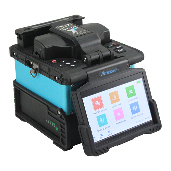
Optical Fusion Splicer Instruction Manual 4. Description and Function of Splicer 4.1 Components of Splicer Heating tube 炉 Wind Protector Battery LCD Screen 屏 Fig.4.1.1 Main host USB Port Power Port 口 口 Fig.4.1.2 Power port... - Page 15 Optical Fusion Splicer Instruction Manual Wind protector LED Light V-groove Electrodes Electrodes cover Objective Lens Fixture Fig.4.1.3 Splicing components Heat V-groove Heat V-groove Fig.4.1.4 Heating stove Optical fiber press foot...
- Page 16 Optical Fusion Splicer Instruction Manual 4.2 Keyboard and Function 4.2.1 Keyboard 4.2.2 Key Definitions Keyboard Icon Name Function Start/stop Power on/off Heating key Start heating Switch X/Y view Switch the X/Y views after field fiber alignment Enter menu, and confirm Menu/Confirm the operation Reset...
-
Page 17: Panel And Interface Instructions
Optical Fusion Splicer Instruction Manual Panel and Interface Instructions 1. Power Supply The fusion splicer supports two types of power supply: a. Internal battery supply power (no external adaptor is used) b. External adaptor supply power (A power adaptor is used) Note: Please use the standard adaptor which is packed along with fusion splicer, if use other model of adaptor, may result in abnormal running. - Page 18 Optical Fusion Splicer Instruction Manual b. Battery charge When the adaptor is connected, it will charge to the battery, user can check the battery icon to judge whether the fusion splicer is charging, the charge time will change along with battery electricity, max.
-
Page 19: Power On/Off
Optical Fusion Splicer Instruction Manual 2. Power On/Off 2.1 Power On Press in short time, the power indicator on operation panel turns red, the buzzer beeps, all motor back to initial position, and the LCD screen shows the optical fiber checking interface, as fig 2.2.1 shows. - Page 20 Optical Fusion Splicer Instruction Manual chapter. Press MENU enter into main menu interface, as Fig.3.1 Fig.3.1 Main Menu Function Menu Specification Function Setting Setting parameters of fast ARC, tensile testing etc. Splice Mode Setting parameters under splicing mode Heating Mode Setting parameters of heating process, time, temperature, heating shrink etc.
-
Page 21: System Setting And Function Setting Menu
Optical Fusion Splicer Instruction Manual 4. System Setting and Function Setting Menu Fig.4.1 System Setting Menu Setting Description Adjust Display Adjust the screen’s brightness Backlight Language Adjust the language, such as Chinese, English etc. Screen can rotate in 180° to suit different Screen Reversal direction working Set Time... -
Page 22: Preparation Before Splicing
Optical Fusion Splicer Instruction Manual Function Description Quick ARC If this function is turned on, before splicing, Calibration the fusion splicer will run a quick ARC Mode calibration If Tension test is turned on, after splicing, Tension Set Tension test will be executed automatically If Tension test is turned off, after opening Reset Waiting cover, the fusion splicer auto to reset waiting... - Page 23 Optical Fusion Splicer Instruction Manual Fig 5.1.1 Strip indoor fiber ○ ○ 2 Shear the string with a scissor 1 Strip outer plastic with stripper Strip inner plastic with stripper ○ ○ 4 Strip coating with stripper 4 Stripped coating with stripper Fig 5.1.2 Strip other type of optical fiber 5.2 Install Heating Sleeve After the optical fiber splicing, a heating sleeve is needed to...
- Page 24 Optical Fusion Splicer Instruction Manual Fig 5.2.1 Install heating sleeve 5.3 Strip and Clean the Optical Fiber Coating a. Strip the coating Strip the fiber’s coating with a stripper, the length is about 30mm, as Fig.5.3.1&5.3.2 shows. Place the coating stripped fiber into the fixture groove, the length is about 30mm.
- Page 25 Optical Fusion Splicer Instruction Manual Fig 5.3.2 Strip the coating manually b. Clean the optical fiber After stripping the coating, use gauze (dipped in alcohol) cotton ball to clean the bare fiber, toward to bare fiber and rotate the ball to clean the chips.
- Page 26 Optical Fusion Splicer Instruction Manual b. Align the optical fiber coating layer edge to appropriate scale mark, place optical fiber into oriented rolling groove of holder, and confirm that bare optical fiber is straightly placed on the clamp pad. c. Close clamps cover of holder first then close the top clamp cover slowly, quickly push the sliding plate with blade to another side, and finish optical fiber cleaving.
- Page 27 Optical Fusion Splicer Instruction Manual end of each fiber is located between the v-groove edge and tip of electrode. If fiber coating has any curl, place optical fiber and make its curve is turned upwards. Be careful to avoid the prepared optical fiber ends touched any objects, so that optical fibers end -surface quality can be guaranteed.
-
Page 28: Splicing Operation
Optical Fusion Splicer Instruction Manual 6. Splicing Operation 6.1 Choose Splice Mode, Edit Splice Parameters a. Splice mode description Splice Mode Description SM (single mode), MM (multi-mode), DS (dispersion), NZDS (non-zero dispersion), Fiber Type BIF/UBIF EDF etc., Factory defined multi default groups, user can choose different splicing program with fiber type. - Page 29 Optical Fusion Splicer Instruction Manual Manual ReARC Set the ReARC time. With some situation, Time splice loss can be reduced by ReARC. Set Refined, clad and Core alignment, default Align Type core alignment. Quick Splice Can be set On/off, if open, splice time will at Mode min.
- Page 30 Optical Fusion Splicer Instruction Manual Splicer Description Parameters Set the Prefuse time between time of ARC Prefuse Time and fiber pushing. Prefuse ARC Set the Prefuse ARC current between time of Current ARC and fiber pushing. Splice Time Set splice ARC time. ARC Current Set splicer ARC current Overlap...
- Page 31 Optical Fusion Splicer Instruction Manual aligning, the screen shows left and right fiber angle. If the detected end face cleave angle exceed limitation value, an error message also shows, user need to re-cleave fiber again. Note: Set the “End-face Angle Limit” “Fiber Align Limit” in “Splice Mode”...
- Page 32 Optical Fusion Splicer Instruction Manual Left and right Reload fiber, Re-load fiber is cleaved re-cleave fiber too long. fiber Problem occur Unqualified while cleaving Re-cleave fiber end fiber (concave fiber face core, bulge tip, bevel, burr etc.) Re-clean Unqualified Dust on the fiber, and fiber surface of fiber...
- Page 33 Optical Fusion Splicer Instruction Manual 6.4 Splice Loss and Quality Evaluate After splicing, the splice loss evaluation value will show on the right screen, if the fiber is spliced abnormally, such as fiber thick, thin, separation, bubbles, line etc. an error message will appear, user have to re-splice or re-ARC.
- Page 34 Optical Fusion Splicer Instruction Manual 1. Bad angle of fiber 1. Re-load or re-clean end-face fiber 2. Dust on fiber end face 2. Increase Perfuse 3. Prefuse in lower Bubbles current or time. current or shorter time 3. Increase splice 4.
-
Page 35: Tension Test
Optical Fusion Splicer Instruction Manual 7. Tension Test If “Tension Test” is turn on, after finishing splicing, Tension Test will be executed automatically, Tension=2N, the menu as below: Fig 7.1 Tension Test Menu 8. History Records Fig 8.1 History Records Menu... - Page 36 Optical Fusion Splicer Instruction Manual History Description Records Total ARC Count the ARC total times from last Reset Count Reset ARC Change the electrodes, execute this Counter operation Total Spliced The statistic of stored splice records Provide max. 10000 groups new splice Splice Records records.
-
Page 37: Heating Mode
Optical Fusion Splicer Instruction Manual 9. Heating Mode Enter “Heating Mode”, as Fig 9.1 shows: Fig 9.1 Heating Mode Menu Heating Mode Description Different heating mode is set for Heating Mode No. different sleeve, 30 group user define program Sleeve Type 10mm-60mm sleeve, FC、SC Sleeve Diameter 1-8mm... - Page 38 Optical Fusion Splicer Instruction Manual Note: Use the pre-set heat parameters, if the sleeve type is “Blank”, system will auto-set the heating No. to “1”. After changing electrodes, updated program, user must do shrink calibration to avoid influencing shrink result. a.
-
Page 39: Maintenance
Optical Fusion Splicer Instruction Manual Maintenance 1. Maintenance Menu Fig 1.1 Maintenance Menu Maintenance Description Operate ARC, and auto-calibrate ARC ARC Calibration current Run repeatedly high current ARC to Clean Electrodes clean electrodes After replace electrodes, auto-detect Replace Electrodes ARC location and ARC repeatedly to stabilize electrodes. -
Page 40: Arc Calibration
Optical Fusion Splicer Instruction Manual 2. ARC Calibration When splicing the fiber, environmental factors, such as temperature, humidity, atmospheric pressure etc. may lead to the change of ARC strength. This fusion splicer is equipped with a temperature and atmospheric pressure sensor to detect the above factors and ensure a stable working environment. -
Page 41: Electrodes Maintenance
Optical Fusion Splicer Instruction Manual c. Press to calibrate ARC. (1). System set the fiber gap to ARC central spot which can be detected. (2). After ARC, system will detect the right and left fiber’s splice value, and calibrate ARC current. d. -
Page 42: Detect System Parameters
Optical Fusion Splicer Instruction Manual 3.2 Replace Electrodes Electrode will be abraded in long term using, for used about 5000 times, it is recommended that replace the electrodes to avoid increase splice loss and decrease the splice strength. There will be a replacing prompt after over 5000 times, after replacing, user need to operate “Clean Electrodes”... -
Page 43: Clean Fusion Splicer
Optical Fusion Splicer Instruction Manual violently Continuously splicing failure or splice loss higher Failure in fiber aligning process. Operation step as below: a. Clean V-groove and cleaved fiber with a dipped alcohol gauze. This is an important step, user must operate. b. -
Page 44: Program Upgrade
Optical Fusion Splicer Instruction Manual Splicer adopts high precision image application technique to locate and align optical fiber, while the dust adhering to lens shall interfere with processor in terms of image processing; accordingly, dirty lens shall adversely influence the splicer in terms of location of optical fiber core and lead to higher splicing loss or splicing failure;... - Page 45 Optical Fusion Splicer Instruction Manual user can upgrade the system to newest program via this operation. Operation step as following: a. In “System Setting” menu, find “About” and enter the info. review page, user can find the current version info. (such as: V5.01/V2.28/ROM: V0.80) b.
- Page 46 Optical Fusion Splicer Instruction Manual Appendix 1 Warning Info. List Warning Cause Solution 1. For cause 1&2, re- 1. Left fiber is cleaved cleave left fiber for too short correct length. Left fiber 2. Left fiber loaded in V- 2.
- Page 47 Optical Fusion Splicer Instruction Manual 1. Dust on right fiber Right fiber 2. Bad quality for right As the same with LFNQ unqualified fiber, such as damage of solution (RFNQ) fiber core or cladding, incomplete fiber etc. Left and right fiber Same with above Same with above method...
- Page 48 Optical Fusion Splicer Instruction Manual limited value groove, re-operate “ARC 2. Mismatching fiber Calibration” and re-splice splice mode is chosen 2. For cause 2, replace to proper splice mode Current battery Connect power adaptor Low power Electricity is low than to charge Operate “Replace Replace...
- Page 49 Optical Fusion Splicer Instruction Manual mechanical structure electrodes. After above is damaged. step, the problem isn’t solved, contact with factory directly Keep splicing, no effect on splice result. If Fusion splicer works in Abnormal data problem is appear an abnormal status continuously, re-start fusion splicer 1.
- Page 50 Optical Fusion Splicer Instruction Manual storage normally directly. Re-start the fusion Abnormal splicer, if the prompt still COMM. exist packet loss COMM. show, contact with factory directly Re-start the fusion Camera lens may be Abnormal splicer, if the prompt still damaged or the relevant image show, contact with...
- Page 51 Optical Fusion Splicer Instruction Manual Appendix 2 Error Message List Error Reason Solution Message Abnormal Incorrectly install Re-install electrodes strictly sound when the electrodes comply with request run ARC 1. Incorrectly install 1. Re-install electrodes the electrodes ARC delay or strictly comply with request 2.
- Page 52 Optical Fusion Splicer Instruction Manual 1. Re-prepare optical fiber and re-splice 1. Dust on fiber 2. Choose the right fiber Bad quality of 2. Choose the wrong type or splice mode splicing spot fiber type or splice 3. Do ARC Calibration, adjust mode to proper ARC strength.
- Page 53 Optical Fusion Splicer Instruction Manual Appendix 3 Guaranty Guarantee period and condition If the splicer shows a quality issue within warranty period after the date of delivery, the free maintenance service will acceptable by manufactory; however, free maintenance service will be refused if following conditions happens: Failure or damage as a result of natural disaster.
Need help?
Do you have a question about the SAT-17T and is the answer not in the manual?
Questions and answers