Table of Contents
Advertisement
Advertisement
Table of Contents

Summary of Contents for HeatPumps4Pools LCSPC-40
-
Page 2: Table Of Contents
TABLE OF CONTENT INTRODUCTION…………...………………………………………………………………………………………………..2 This manual……………………………………………………………………………………………………………………... 2 ………………………………………………………………………………………………………..The Heat Pump ..SAFETY INSTRUCTIONS ……………………………………………………………………………………………………. 3 ……………………………………………………………………………………………………………………….……. 3 Warning ……………………………………………………………………………………………………………………………. 4 Caution… CONTENTS……………….…………………………………………………………………………………………….………... 5 OVERVIEW OF THE UNIT ……………………………………………………………………………………….…………. 6 EXPPLODED VIEW ………………………………………………………………………………………….…………………. 7 INSTALLATION …………………………………………………………………………………………….…..….…….…….. 8 …………………………………………………………………………………………….…..………. 8 Installation guidelines ….……………………………………………………………………………….…………………………... -
Page 3: Introduction
INTRODUCTION This manual This manual includes the necessary information to safely install and maintain your Heat Pump. Please read this manual carefully before you operate the unit. The Heat Pump The swimming pool heat pump is one of the most economical ways of heating your swimming pool efficiently. -
Page 4: Safety Instructions
SAFETY INSTRUCTIONS To prevent injury to the user, other people or damage to property, the following instructions must be followed. Install the unit only when it complies with local regulations, by-laws and standards. Check the main voltage and frequency. This unit must be earthed and have a supply voltage of 220 – 240 V ~ / 50Hz. The following safety precautions should always be taken into account: Be sure to read the following WARNING before installing the unit. -
Page 5: Caution
Do not install the unit in a place where there is a chance of flammable gas leaks. In the event of a gas leak, if gas accumulates in the area surrounding the unit, it could cause an explosion. Water Connections. All plumbing connections should be carried out as per the instructions in this manual. -
Page 6: Contents
CONTENTS Before starting the installation, please make sure that all items are found inside the box. The Unit Box Item Image Quantity Swimming pool heat pump Operation and Installation Manual Accessories 1(Set) -
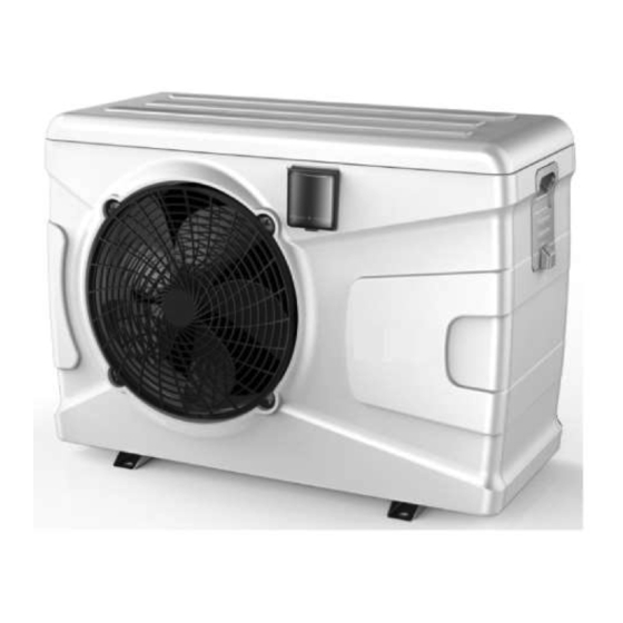
Page 7: Overview Of The Unit
OVERVIEW OF THE UNIT EXPLODED VIEW(ECO-30,55,70) -
Page 8: Expploded View
EXPLODED VIEW Top cover Wired controller Electrical box Compressor Support frame 4-way valve assembly Evaporator Right panel Left panel Handle Fan bracket Titanium heat exchanger Fan motor Gas gauge Fan blade Grill 10 Front panel... -
Page 9: Installation
INSTALLATION Installation guidelines The following information is for guidance only. Locating the Unit The unit should be located on a solid, flat, horizontal surface. Ensure 3 meters of free air flow to the discharge panel and 1 meter to the inlet panel. Ensure adequate access to the controller and for maintenance purposes. -
Page 10: Electrical Connection
The Electrical supply must correspond to that indicated on the appliance. All supply cables have to be sized according to the appliance power and installation requirements. Please refer to below table: Heat Pump Cable Size 3x1.5mm LCSPC-40/55 3x2.0mm LCSPC-70 3x2.0mm LCSPC-95 3x2.5mm LCSPC-120 3x2.5mm... -
Page 11: Easy Control (Touch & Go)
Easy control (Touch & GO) 1. Turn ON/OFF (1) Turn ON: When the heat pump is OFF, press “ ” to turn on the heat pump. Press “ “ OFF mode ON mode (2)Turn OFF: When the heat pump is ON,press “ ”... -
Page 12: Operating The Unit
OPERATING THE UNIT This is achieved via the Digital Controller. NEVER LET THE DIGITAL CONTROLLER GET WET. THIS MAY CAUSE AN ELECTRIC SHOCK OR FIRE. NEVER PRESS THE BUTTONS OF THE DIGITAL CONTROLLER WITH A HARD, POINTED OBJECT. THIS MAY DAMAGE THE DIGITAL CONTROLLER. NEVER INSPECT OR SERVICE THE DIGITAL CONTROLLER YOURSELF. -
Page 13: User Interface
User interface Icon Function Auto Mode This icon will show if unit is on and in Auto mode. This icon will show if unit is on and in Cool mode, the unit will cool Cool Mode the water until the set temperature is reached. Defrosting This icon will show when unit entering into defrosting mode. -
Page 14: Buttons
Button Function ON/OFF Press once to turn unit On or Off. MODE To select unit running mode. Press once to increase set temperature by 1℃, or increase parameter data by 1 unit. Press once to decrease set temperature by 1℃, or decrease parameter data DOWN by 1 unit. -
Page 15: Lcd Icons
Setting button These are the multi-purpose buttons. Combining with the buttons, they are used for parameter setting, parameter checking, and adjustment of the timer. LCD icons 1. Cooling mode This icon indicates that the current operation mode is cooling. 2. Heating mode This icon indicates that the current operation mode is heating. -
Page 16: Controller Operations
Controller operations 1. Parameter checking and setting. Press button for 10 seconds to enter the parameter checking interface, then press Enter the parameter settings. You can now adjust parameters value with . Then press save and switch to other parameter settings. NOTES: Press button for 10 seconds to enter parameter checking and adjusting status. -
Page 17: Parameter Checking And Adjustment
PARAMETER CHECKING AND ADJUSTMENT Parameter list Some parameters can be checked and adjusted by the controller. Below is the parameter list. Parameter Name Range Default Remark Memory function if power off 0(no)\1(yes) Adjustable Timer cycle (every day or once) 0(once)\1(every day) Adjustable 2-10℃... -
Page 18: Error Codes
Pump-off time after reaching setting 3-20MIN Adjustable water temp. Second anti-freezing mode 0(Heat pump)\ Invalid 1(Electric heater) Unit mode selection 0(cooling only)\1(cooling Adjustable and heating)\2(heating only) Inlet water temp -9~99℃ Actual Outlet water temp -9~99℃ Actual Coil temp. -9~99℃ Actual Exhaust gas temp -9~99℃... -
Page 19: Maintenance
Undercharged refrigerant Add some refrigerant Capillary block Replace the capillary Low pressure protection Poor connection of pressure switch Reconnect the switch Pressure switch failure Replace the pressure switch Main PCB damaged Replace the PCB This function occurs when ambient temp First step anti-freeze protection in Winter No action needed is too low and unit is in standby... -
Page 20: Troubleshooting
twigs, etc.) before each new heating season. These can be manually removed using compressed air or by flushing with clean water. It may be necessary to remove the unit cover and air inlet grid first. Attention: Before opening the unit, ensure that all electrical supplies are isolated. To prevent the evaporator and the condensate tray from being damaged, do not use hard or sharp objects for cleaning. -
Page 21: Environmental Information
The timer works but the programmed actions are executed at the wrong time (e.g. 1 hour too late or too early). Please check whether: ➢ The clock and the day of the week are set correctly, adjust if necessary. If you cannot correct the fault yourself, please contact your after-sales service technician. Work on the heat pump may only be carried out by authorized and qualified after-sales service technicians. -
Page 22: Wiring Diagram
WIRING DIAGRAM Please refer to the wiring diagram on the electric box. Models: LCSPC-40, LCSPC-55, LCSPC-70, LCSPC-95... - Page 23 Models: LCSPC-120, LCSPC-150, LCSPC-170...
- Page 24 Models: LCSPC-210...
-
Page 25: Technical Specifications
TECHNICAL SPECIFICATIONS Swimming pool heat pump (ABS plastic casing) LCSPC- LCSPC LCSPC LCSPC LCSPC- LCSPC- LCSPC- LCSPC- Condition capacity 4.15 5.58 7.11 9.72 12.11 15.18 17.21 21.27 Ambient (KW) 24℃ power 0.67 0.93 1.18 1.60 1.85 2.40 2.80 3.53 Water 26℃ input(KW) in, 28℃... -
Page 26: Contact Details
Contact details HeatPumps4Pools Ltd Rosemary Lodge Church Road Ramsden Bellhouse Essex CM11 1RT United Kingdom Tel +44 1268 206560 www.HeatPumps4Pools.com enquiries@heatpumps4pools.com...
Need help?
Do you have a question about the LCSPC-40 and is the answer not in the manual?
Questions and answers