
Summary of Contents for RLH Industries RLH-ESM1608-04-1
-
Page 1: User Guide
RLH Industries, Inc. 16+8 Industrial Managed Ethernet Fiber Switch User Guide U-044 2017A-0425... - Page 2 RLH Industries, Inc. Copyright © 2014 RLH Industries, Inc. All rights reserved. No part of this document may be copied or distributed without permission. The RLH logo may not be used for commercial purposes without the prior written consent of RLH and may constitute trademark infringement.
-
Page 3: Table Of Contents
Contents 1. Important Information Intended Audience Conventions General Safety Practices 2. Introduction Product Description Standard Features Application Diagram Front Panel Front Panel Components Front Panel LEDs Rear Panel Rear Panel Components Power Input Download Program Port Communication Ports 10Base-T /100Base-TX Ethernet ports 100Base-FX fiber port 3. Before Installing Observe Special Handling Requirements... - Page 4 4. Quick Start Guide Easy Installation Install the Switch Connect power Connect fiber cables Connect ethernet cables 5. Configuring the System Managing with Hyper Terminal Modification of IP Address Web Management Network Setting Startup and Log in System Status System Status Port Configuration Broadcast Storm Suppression L2 Features...
- Page 5 Port Statistics Rx Frame Statistics Tx Frame Statistics Traffic Statistics MAC Address Diagnosis Port Mirroring Diagnosis System Device IP IP Address Subnet Mask Default Gateway DNS Address System File Update Logout Exit from the WEB interface. Default Settings 6. Specifications General Specifications 7. Troubleshooting First Step: Isolate the problem...
-
Page 6: Important Information
1. Important Information Intended Audience This manual is intended for use by knowledgeable telco/network installation, operation and repair personnel. Every effort has been made to ensure the accuracy of the information in this manual is accurate. However, due to constant product improvement, specifications and information contained in this document are subject to change without notice. -
Page 7: Introduction
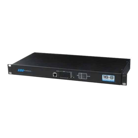
2. Introduction Product Description The RLH Managed Ethernet Switch is a smart managed switch that offers 16 10/100Base-T(x) RJ-45 TCP ports together with 8 100Base- FX fiber connectors. The optical interfaces may be dual fiber single mode or multimode, or bi-directional single fiber, and have a transmission up to 120Km/74 miles. The switch can be managed through it’s imbedded Web Interface, with simplified settings accessible through the console port, and also supports external alarm functions for alarm input monitor purposes. -
Page 8: Application Diagram
VIDEO SERIAL MODBUS DEVICE RS-422/485 DEVICE SERIAL DEVICE Front Panel Not Used Link/ACT Not Used CONSOLE RLH Industries, Inc. FIBER RJ-45 TCP RJ-45 TCP FIBER ALARM MANAGED ETHERNET SWITCH TEST 3 4 5 6 Front Panel Components Item Description Console Port... -
Page 9: Front Panel Leds
Activity is detected and data is being transmitted Network connection of the port is not valid Note: The alarm condition is set through the management software. Rear Panel MANAGED 24 PORT RLH Industries, Inc. ETHERNET FIBER SWITCH fiberopticlink.com N/– ALARM RELAY... -
Page 10: Download Program Port
Download Program Port The RLH fiber switch has 1 download program port (RJ45 type) designated CONSOLE on the front panel, It manages the system with PC through RJ45-DB9F adapter. Communication Ports The switch has 16 10/100BaseT(X) Ethernet ports and 8 100M fiber ports. The pinout of the RJ45 ports connect to UTP or STP. -
Page 11: 100Base-Fx Fiber Port
MDI (straight-through cable): MDI-X (Cross over cable): 100Base-FX fiber port 100Base-FX port works with full-duplex, SM or MM SC/ST. The fiber port may contain single fiber bidirectional connectors, or dual fiber connectors. Dual fiber connectors must be used in pairs. The TX (transmitting) port connects to the remote switch’s RX (receive) port;... -
Page 12: Before Installing
3. Before Installing Observe Special Handling Requirements Be careful when handling electronic components ATTENTION ELECTROSTATIC SENSITIVE DEVICES • This product contains static sensitive components. • Handle the modules by their faceplates only, do not touch the circuit boards or components. •... -
Page 13: Prepare For Installation
Prepare for Installation Check for shipping damage Carefully unpack and inspect the unit and accessories. Contact RLH immediately if any components are damaged or missing. Electronic components, fiber optic cable, and accessories have special handling requirements to prevent damage and enhance system reliability. If the switch will be relocated in the future, save the cartons and protective packaging material. -
Page 14: Site Requirements
Site Requirements Site selection Locate the switch to allow easy access to the equipment. Leave at enough clearance in the front and rear to gain access to the fiber, ethernet alarm and power connections.Typical application environments Route the fiber optic cable to the installation area before installing the switch. Required power sources You will need an acceptable power source. -
Page 15: Quick Start Guide
4. Quick Start Guide Easy Installation Before starting 1. Important Information • Review the safety information in section • Familiarize yourself with the fiber switch as described in section Introduction • Know how to handle fiber optic cable, have a suitable installation environment with the correct power, as described 3. -
Page 16: Configuring The System
5. Configuring the System Managing with Hyper Terminal Connect the switch to a PC running Windows®, then open Hyper Terminal: Start->Program->Attachment-> Communication. Make a new connection when opening Hyper Terminal. The communication port needs to connect the PC to the switch. It must use the following configuration parameters: Bits per second: 115200, Data bits: 8, Parity: None, Stop bits: 1, Flow control: None. -
Page 17: Modification Of Ip Address
Modification of IP Address When Hyper Terminal is finished, you can see the following screen: Terminal Window $$ means user enters into restricted privileges mode; # means user enters into manager mode; The two modes use command root and command exit to switch mode. The default password of the switch is "admin: admin". -
Page 18: Web Management
Web Management The RLH-ESMXXX-XX-X series switch supports Web management. It is very intuitive to manage and maintain the equipment through Web interface. Before configuring the switch, please ensure necessary software installed your computer and reasonable configuration of the network. The lowest requirement for user's computer is as below: •... -
Page 19: Startup And Log In
TCP/IP Properties Screen Startup and Log in Open IE, input http://192.168.1.254 in the address field, click “Enter” as shown below: Input correct user name and password, then enter successfully (default user name is “admin”, password is “admin”. If user name or password input incorrectly in 3 times continuously, you must login again. Note: User name and password are case-sensitive. -
Page 20: System Status
System Status Menu Introduction Menu Bar consists of 8 parts: system status, port configuration, L2 Feature, Qos, Redundancy, Monitor, Port Statistics, Diagnosis and basic settings. Web Overtime Handling If user doesn't operate the Web interface for a long time, The system will cancel this login (but configuration change made in this login will be saved in Web configuration interface). -
Page 21: System Status
on Web configuration interface again, the system will reminds user and returns to the login dialog box. Users need to log in again if operating is needed. System Status Device Information mainly display the basic information of RLH-XXXXXX-XX-X series switch including: Name, Serial No., Description, Contact Information, MAC address, Hardware Version and Firmware Version, as shown in below: Among them, Model, Hardware Version, Firmware Version and MAC address can’t be changed. - Page 22 We can also see each port status in the Port Information area. Port Information Screen • Connection: LINK or LOS • Port Status: FULL (Full duplex) or HALF (Half duplex) • Speed: 10M or 100M • Port Type: Tx or Fx Configuring the System...
-
Page 23: Port Configuration
Port Configuration Main function of port settings: • Forcibly set up speed mode and duplex mode of each port • Enable or disable each port • Each port is allowed flow control or not. Port Configuration Screen Configuring the System... - Page 24 This interface displays basic information of each port. The meaning of information is shown as below: Port Setting Notes Port Speed Port speed shows the connecting speed of the port. It includes 3 kinds of speed: 10M, 100M and auto- negotiation.
- Page 25 negotiation so that the port can automatically judge the connection type of the device connected to it and automatically adjust the connection type to ensure the maximum compatibility. Flow Control Flow control is used to prevent the frames from discard while port is blocked. This method is to send back the blocking signal to its original address while sending or receiving buffer area start to overflow.
-
Page 26: Broadcast Storm Suppression
The device provides both ingress and egress speed limitation. The ingress speed refers to the actual speed from PC and other devices to the switch. The egress speed refers to the actual speed from the switch to other devices. If ingress and egress speed of the connecting port between two devices are limited at the same time, the actual speed will be the smaller value. -
Page 27: L2 Features
There are many reasons to cause broadcast storm. For example: a redundant or incorrect connect among switches. If storm suppression is enabled, it can stop the attack. Our device can detects 2 kind of broadcast messages according to the type of broadcast storm. •... -
Page 28: Port Based Vlan
Each VLAN is a broadcast domain and hosts in VLAN can communicate just like in the same LAN. But it can not interconnect between VLAN. Then broadcast message is limited in the VLAN. Port based VLAN A port based VLAN determines the membership of a data frame by examining the configuration of the port that receive the transmission or reading a portion of the data frame's tag header. - Page 29 1. Add Item Group name can be number only in IEEE 802.1Q VLAN. It is TPID in VLAN ID. The same group name means you need to modify the members of the group. A new group name means the new transmission rule is built. The transmission item is not more than 64 in IEEE 802.1Q VLAN.
-
Page 30: Igmp Snooping
• Keep the same VID and priority If the data has no VLAN ID, please use the default priority and port VID to create a VLAN ID and insert it into the data frame, otherwise the data frame keeps the same. •... - Page 31 IGMP Notes • It must set up 802.1Q VLAN first before enabling IGMP Snooping. • It had better not to have many IGMP query to save the resources. If you are not sure of the forwarding relationship of the unknown multicast group, please choose all the ports. Static Multicast FWD The device provides the function of static MAC address forwarding.
-
Page 32: Qos
QOS Classification QoS can provide 4 internal queues and each queue supports 4 different levels of traffic. The data packets with high priority stay a short time in the ethernet switch. Some traffic which is sensitive to delay will supports very short latent period. According to port ID, MAC address, 802.1p priority tag, DiONetServ and IP TOS, the device can classfy data packets to its corresponding classification. -
Page 33: Cos
Default priority is also the port based priority. Default priority is quite different from COS and TOS, it has nothing to do with data packets but port priority of the switch. When port priority is high, the data packets transmitted from this port will faster than other ports. Priority tag in 802.1P includes 8 kinds (0-7). -
Page 34: Redundancy
Note If the default priority is High, then other QoS property will not be checked and put into High priority queuing DSCP is lower than default priority, if there is no settings about DSCP, 802.1P will be checked, or the queuing will be based on DSCP settings. - Page 35 The device supports 2 Trunking groups. Each group support 2-4 port trunking. Trunking Notes The action of Trunking member is the same, so configuration sub-items of each member (port properties, VLAN properties) are the same in a group. If you don't confirm RSTP status, please disable RSTP,or close the others, leaving one RSTP channel. Port 1 as a system reservation cannot be used as Trunking port.
- Page 36 Basic interface of Rapid Ring as shown in the following figure: Basic interface shows Protocol of Redundancy is None. Ring can be set by Protocol of Redundancy configuration if it is needed. As shown in the figure below, in [Settings] area there are 2 kinds in corresponding drop-down menu of Protocol of Redundancy: Ring V2 and Ring V3.
-
Page 37: Single Ring Configuration Of Ring V2
2. Ring V2 supports 4 Ring groups available for sing ring and coupling ring. As shown in the following figure. 3. Click Apply and it will take effect after system reboot. Single Ring Configuration of Ring V2 1. Enable Ring V2. Choose Ring V2 in [Settings] area, as shown in figure 6-25. 2. -
Page 38: Coupling Ring Configuration Of Ring V2
Coupling Ring Configuration of Ring V2 Basic structure of coupling ring is shown in the following figure. Operating Method 1. Select Ring V2 in Settings area and enable Ring Group 1 and 2;(Hello_time can be disable too, if it enable, time of sending Hello packet could not be very fast, or it will influence CPU dealing speed.);... - Page 39 4. Set up Port 7 and 8 of Device 107, 108, 109 to be Ring Ports in Ring Group 1 , Network ID is 1, Ring Type is Single; Set up Port 7 and 8 of Device 102, 103, 104 to be Ring Ports in Ring Group 1, Network ID is 2, Ring Type is Single.
-
Page 40: Ring V3 Coupling
3. Enable Ring 1 (or other Groups), input network ID (0-255 numbers only), choose ring port in Group 1. The Single Ring configuration of Ring V3 is similar to that of Ring V2, so the following page mainly talks about Couple, Chain and Dual homing . -
Page 41: Ring V3 Chain Configuration
3. Set up Port 4 and 5 of Device 100, 101 to be Ring Ports in Ring Group 1, Network ID is 2, Ring Type is Single; Set up Port 1 of device to be Coupling Port in Ring Group 2 , Coupling Control Port is Port 4, Network ID is 3, Ring type is Couple, as shown in figure 6-36. -
Page 42: Access Control
3. Set up Port 7 and 8 of Device 107, 108 and 109 to be Ring Ports in Ring Group 2, Network ID is 2. Ring Type is Chain; as shown below 4. Use a wire to connect Port 7 and 8 of Device 107-109 in turn to make a chain. Use a wire to connect Port 7 and 8 of Device 100-103 in turn to make a Single Ring, Then use a wire to connect Port 8 of Device 107 and Port 7 of Device 109 to normal port of Device 102 and 103. -
Page 43: Access Profile
Note: If you forget the login name and password, please contact our technical support. Access Profile Web Server Transfer Protocol • HTTP HTTP (Hyper Text Transfer Protocol) is an application protocol for distributed, collaborative, hypermedia information systems. HTTP is the foundation of data communication for the WorldWide Web. •... -
Page 44: Static Unicast Fwd
Note It must enable at least one protocol in HTTP and HTTPS. Some explorer cannot display normally when it use HTTPS at the first time. It will display normally after afresh. The IP address must be valid. At least one address and the IP address are in the same network segment. Otherwise the device is invalid. - Page 45 Button [add] and [delete] are used to add and delete MAC address. Static MAC Address asks the user to input a valid address, if the MAC address is invalid, the warning information ejects. Static Unicast Address is used to choose the transfer port of static MAC address. It can appoint one or more transfer ports. Click [add] and [delete] to update the static MAC address.
-
Page 46: Port Statistics
Port Statistics Rx Frame Statistics Unicast Numbers of the unicast data packets received by the port Multicast Numbers of the multicast data packets received by the port Broadcast Numbers of the broadcast data packets received by the port Drop Number of discarded normal data packets because of safety control Pause Ethernet control frames of protocol 0x8808 received by the port, in full duplex mode, this data packet is used to control frequency of data sending. -
Page 47: Tx Frame Statistics
Tx Frame Statistics Unicast Numbers of the unicast data packets sent by the port Multicast Numbers of the multicast data packets sent by the port Broadcast Numbers of the broadcast data packets sent by the port Drop Number of discarded normal packets because of lack of resources or not meeting analytic conditions (excluding discarded packets because of conflict) Pause Ethernet control frames of protocol 0x8808 sent by the port, in full duplex mode, this data packet is used to... -
Page 48: Traffic Statistics
Traffic Statistics Number of bytes of all data packets sent by the port Number of bytes of all data packets received by the port Unicast Number of unicast data packets sent and received by the port Multicast Number of multicast data packets sent and received by the port Broadcast Number of broadcast data packets sent and received by the port Error... - Page 49 MAC address includes 3 kinds: 1. Dynamic MAC address DDynamic MAC address is created by data frames learning in the network. It will be deleted when it is beyond maximum age. When the port of the switch connected to the device has changed, the corresponding MAC address in the MAC address table also change.
-
Page 50: Diagnosis
3. Permanent Static MAC address Permanent MAC address is generated by configuration. It is beyond maximum age. Whatever changes the ports of the switch make, the relationship of the MAC address and corresponding port will never change. Permanent MAC address will disappear when the switch re-start. MAC address table can appoint type of the order. -
Page 51: Diagnosis
Mirror Port It defines a group of ports which are needed to be monitored. The device collects data from these ports. Monitored Port It defines a group of ports which are used to monitor other ports. The device outputs the data through these ports. -
Page 52: System
Host Address AAppointed computer need to ping, it can be an IP address or a domain. Message Size Echo data packet including data in "message length" Message Number Number of appointed echo data packet Message Interval Appointed message sending interval, the unit is ms. Response Timeout Timeout interval, the unit is ms. -
Page 53: Default Gateway
Default Gateway Default gateway in the host PC is generally called default route. Default route refer to a kind of router that destination address of IP data packet will choose when it don’t find other existing route. All data packets of destination address which don’t exist in the list of router will choose default route. - Page 54 1. Factory Default If you know the IP address of the device, user name and password: Use IE to login Web interface. Click "System Management" Click "System File Update" Choose "Factory Default" Click "OK" Notice: the IP address will be "192.168.1.254". Open a new interface, input "192.168.1.254"...
-
Page 55: Logout Exit From The Web Interface
4. Upload Configuration If you know the IP address of the device, user name and password: • Use IE to login Web interface. • Click "System Management" • Click "System File Update" • Choose "Upload Configuration" • Click "Upload" 5. Upgrade Firmware If you know the IP address of the device, user name and password: •... - Page 56 Click “Cancel” you will logout the interface. You will see a message stating that “access is unauthorized”. Configuring the System...
-
Page 57: Default Settings
Default Settings Configuring the System... -
Page 58: Specifications
6. Specifications General Specifications IEEE 802.3,IEEE 802.3u,IEEE 802.3ab,IEEE 802.3z, IEEE 802.1Q, IEEE 802.1D, IEEE 802.1x compliant Standards 16 10/100M TCP ports Ports 8 100 FX 1x9 optical ports MAC address Store & forward architecture and performs forwarding and filtering at non-blocking full wire speed Switching mode IEEE 802.1Q Port-based VLAN VLAN... -
Page 59: Troubleshooting
Reset and test in the factory default mode. If trouble persists, replace the unit and retest. If technical assistance is required, contact RLH Industries, Inc. technical support department: 800-877-1672 (6 am to 6 pm- PST), or call our 24/7 Technical/Customer Service: Toll Free 1-855-RLH-24X7... -
Page 60: Ordering Information
Each unit is identified by the part number. Optics Side Distance Wavelength Fiber Part Number Multimode ST 2 km/1.2 mi 1310nm 62.5 μm RLH-ESM1608-04-1 Multimode SC 2 km/1.2 mi 1310nm 62.5 μm RLH-ESM1608-03-1 Tx 1310nm / 2 km/1.2 mi 62.5 μm RLH-ESM1608-01-1 Rx 1550nm Bi-Directional ... -
Page 61: Support
Technical Support Email: support@fiberopticlink.com 24/7 technical support: Toll Free 1-855-RLH-24X7 Toll Free 1-855-754-2497 Contact Information Corporate Headquarters: RLH Industries, Inc. 936 N. Main Street Orange, CA 92867 USA Phone: (714) 532-1672 Toll Free 1-800-877-1672 Toll Free 1-866-DO-FIBER Fax: (714) 532-1885 Email: info@fiberopticlink.com... - Page 62 RLH Industries, Inc. Please contact your RLH sales representative 936 N. Main Street, Orange, CA 92867 USA for pricing and delivery information. T: (714) 532-1672 Specifications subject to change without notice. F: (714) 532-1885...
Need help?
Do you have a question about the RLH-ESM1608-04-1 and is the answer not in the manual?
Questions and answers