Table of Contents
Advertisement
Quick Links
Advertisement
Chapters
Table of Contents

Subscribe to Our Youtube Channel
Related Manuals for Ditch Witch 8500

Summary of Contents for Ditch Witch 8500
- Page 1 8500 Tracking System Operator’s Manual ® Issue 1.0 053-1254...
-
Page 2: Overview
8500 Tracking System Manual Overview - 1 Overview Chapter Contents Serial Number Location ..... . 2 Intended Use ......3 About This Manual . -
Page 3: Serial Number Location
8500 Tracking System Operator’s Manual Overview - 2 Serial Number Location Serial Number Location Record serial numbers and date of purchase in spaces provided. Serial numbers are located as shown and displayed briefly in lower left corner of tracker and display screens when units are first powered up. -
Page 4: Intended Use
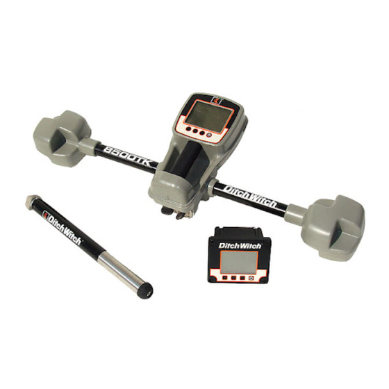
Intended Use Intended Use The 8500 tracking system consists of an 8500TK tracker, an 8500D remote display, and an 850 series beacon. The system provides advanced locating features to 30’ (9 m) deep. It also provides offset locating and depth capability. The system provides projected direction information and offers a Drill-Thru guidance mode. -
Page 5: Fcc Statement - Internal Transmitter
8500 Tracking System Operator’s Manual Overview - 4 FCC Statement - Internal Transmitter FCC Statement - Internal Transmitter Contains FCC ID: TFB-FREESTAR This device complies with Part 15 of the FCC Rules. Operation is subject to the following two conditions: (1) this device may not cause harmful interference, and (2) this device must accept any interference received, including interference that may cause undesired operation. -
Page 6: Foreword
If you sell your equipment, be sure to give this manual to the new owner. If you need a replacement copy, contact your Ditch Witch dealer. If you need assistance in locating a dealer, visit our website at www.ditchwitch.com or write to the following address: The Charles Machine Works, Inc. - Page 7 Copyright 2008 by The Charles Machine Works, Inc. , Ditch Witch, CMW, AutoCrowd, Jet Trac, Roto Witch, Subsite, Fluid Miser, Power Pipe, Super Witch, Pierce Airrow, The Underground, The Underground Authority Worldwide, and Zahn are registered trademarks of The Charles Machine Works, Inc.
-
Page 8: Table Of Contents
8500 Tracking System Operator’s Manual Contents - 7 Contents Overview machine serial number, information about the type of work this machine is designed to perform, basic machine components, and how to use this manual Foreword part number, revision level, and publication date of this manual, and factory contact... -
Page 9: Tracking System Operator's Manual Contents
8500 Tracking System Operator’s Manual Contents - 8... -
Page 10: Safety
8500 Tracking System Operator’s Manual Safety - 9 Safety Chapter Contents Guidelines ....... . 10 Safety Alert Classifications . -
Page 11: Guidelines
8500 Tracking System Operator’s Manual Safety - 10 Guidelines Guidelines Follow these guidelines before operating any jobsite equipment: • Complete proper training and read operator’s manual before using equipment. • Contact One-Call (888-258-0808) and any utility companies which do not subscribe to One-Call. Have all underground pipes and cables located and marked before operating equipment. -
Page 12: Safety Alert Classifications
8500 Tracking System Operator’s Manual Safety - 11 Safety Alert Classifications Safety Alert Classifications These classifications and the icons defined on the following pages work together to alert you to situations which could be harmful to you, jobsite bystanders or your equipment. When you see these words and icons in the book or on the unit, carefully read and follow all instructions. -
Page 13: Safety Alerts
8500 Tracking System Operator’s Manual Safety - 12 Safety Alerts Safety Alerts Electric shock. Contacting electric lines will cause death or serious injury. Know location of lines and stay away. Jobsite hazards could cause death or serious injury. Use correct equipment and work methods. Use and maintain proper safety equipment. -
Page 14: Controls
8500 Tracking System Operator’s Manual Controls - 13 Controls Chapter Contents 8500TK ........14 •... -
Page 15: 8500Tk
8500 Tracking System Operator’s Manual Controls - 14 8500TK 8500TK Icons 1. Beacon battery life indicator 5. Communication indicator 2. Beacon temperature 6. Tracker battery life indicator 3. Beacon roll indicator 7. Frequency indicator 4. Beacon roll value 8. Beacon pitch... - Page 16 8500 Tracking System Operator’s Manual Controls - 15 8500TK Item Description Notes 2. Beacon temperature Displays beacon temperature IMPORTANT: An audible warning is and flashes if temperature activated when beacon temperature is becomes too high. 155°F (68°C). Icon darkens as temperature...
- Page 17 8500 Tracking System Operator’s Manual Controls - 16 8500TK Item Description Notes 8. Beacon pitch Displays pitch of beacon in percent grade or degrees. The arrow behind the value indicates whether pitch is positive or negative.
-
Page 18: Buttons
8500 Tracking System Operator’s Manual Controls - 17 8500TK Buttons Overview 1. Soft button 3. Soft button 2. Soft button 4. Power button Item Description Notes 1. Soft button Function depends on Button is also used to access quick selected mode and is functions. - Page 19 8500 Tracking System Operator’s Manual Controls - 18 8500TK Quick Functions Contrast Adjustment To adjust contrast, press and hold left button (1) and press button 2 to darken/increase contrast or button 3 to lighten/lessen contrast. Backlight Toggle To turn backlight on and off, press and hold left button (1) and press power (4) button. Don’t press power...
-
Page 20: Menu
8500 Tracking System Operator’s Manual Controls - 19 8500TK Menu Overview 1. Display settings 4. System settings 2. Beacon settings 5. Drill-Thru mode 3. Radio options 6. Service menu Item Description Notes 1. Display settings Highlight icon and press See “Display Settings” on page 21. - Page 21 8500 Tracking System Operator’s Manual Controls - 20 8500TK Item Description Notes 3. Radio options Highlight icon and press See “Radio Options” on page 22. select to enter the “radio options” mode. 4. System settings Highlight icon and press See “System Settings” on page 22.
- Page 22 8500 Tracking System Operator’s Manual Controls - 21 8500TK Descriptions Display Settings Description Notes LCD Backlight Controls backlight intensity. Available settings: 0 (off) to 100 (brightest, default). LCD contrast Controls contrast of LCD. Available settings: -20 (lighter) to 20 (darker), 0 is default.
- Page 23 8500 Tracking System Operator’s Manual Controls - 22 8500TK Radio Options Description Notes Radio power Turns radio on and off. Available settings: on (default), off. Channel Sets telemetry channel Available settings: 1 (default) through 15 Tracker Control Enables or disables thrust and rotation of drilling unit.
-
Page 24: 8500D
8500 Tracking System Operator’s Manual Controls - 23 8500D 8500D Icons 1. Beacon battery life indicator 5. Beacon temperature 2. Beacon roll indicator 6. Beacon roll value 3. Communication indicator 7. Beacon pitch 4. Display battery life indicator Item Description Notes 1. - Page 25 8500 Tracking System Operator’s Manual Controls - 24 8500D Item Description Notes 3. Communication Indicates tracker and display indicator are communicating properly. 4. Display battery life Indicates amount of battery indicator power remaining for the display. Flashes when batteries need to be replaced.
-
Page 26: Buttons
8500 Tracking System Operator’s Manual Controls - 25 8500D Buttons Overview 1. Save button 3. Delete button 2. Review button 4. Power button IMPORTANT: • Some icons and functions will change when display is properly connected to TMS Plus. These are shown and explained in the following table. - Page 27 8500 Tracking System Operator’s Manual Controls - 26 8500D Item Description Notes 1. Save button Press to save data for current IMPORTANT: Display must have pipe. received a depth reading from tracker to save. Send button When connected to TMS...
- Page 28 8500 Tracking System Operator’s Manual Controls - 27 8500D Item Description Notes 3. Delete button Press to delete previous pipe data. 4. Power/Menu button To turn on, press once. Press button less than 2 seconds to access menu. To turn off, press for 2 seconds.
-
Page 29: Menu
8500 Tracking System Operator’s Manual Controls - 28 8500D Menu Overview 1. Display settings 4. System settings 2. File management 5. Time/Date settings 3. Radio options 6. Service menu Item Description Notes 1. Display settings Highlight icon and press See “Display Settings” on page 30. - Page 30 8500 Tracking System Operator’s Manual Controls - 29 8500D Item Description Notes 3. Radio options Highlight icon and press See “Radio Options” on page 31. select to enter the “radio options” mode. 4. System settings Highlight icon and press See “System Settings” on page 32.
- Page 31 8500 Tracking System Operator’s Manual Controls - 30 8500D Descriptions Display Settings Description Notes LCD brightness Controls brightness. Available settings: 0 (off) to 100 (brightest, default). LCD contrast Controls contrast of LCD. Available settings: -20 (lighter) to 20 (darker), 0 is default.
- Page 32 8500 Tracking System Operator’s Manual Controls - 31 8500D File Management Description Notes Active file Indicates name of log file that is currently active. Load file Displays a list of log files currently on the SD card. Select a file to make it the active log file.
- Page 33 8500 Tracking System Operator’s Manual Controls - 32 8500D System Settings Description Notes Connect to TMS Plus Activates TMS Plus connected mode. Language Controls displayed user interface language. Available languages include: English, German, Spanish, French, Italian, Swedish, Russian. Date/Time Settings...
-
Page 34: System Operation
8500 Tracking System Operator’s Manual System Operation - 33 System Operation Chapter Contents Beacon Tracking Overview ....34 Setup ........34 Walkover Location Mode . -
Page 35: Beacon Tracking Overview
8500 Tracking System Operator’s Manual System Operation - 34 Beacon Tracking Overview Beacon Tracking Overview Potential radio frequency (RF) hazard. Operating this device within 4” (100 mm) of your body may cause RF exposure levels to exceed FCC RF exposure limits and should be avoided. - Page 36 8500 Tracking System Operator’s Manual System Operation - 35 Setup 5. Select “Roll Calibration” in “Beacon Settings” menu and follow prompts. 6. Select “Pitch Calibration” in “Beacon Settings” menu and follow prompts. 7. Select “Depth Adjustment” in “Beacon Settings” menu and follow prompts.
-
Page 37: Walkover Location Mode
8500 Tracking System Operator’s Manual System Operation - 36 Walkover Location Mode Walkover Location Mode Locate Screen 1. Field balance bar 4. L/R button 2. Signal strength 5. Send button 3. Locate arrows 6. Depth screen button Item Description Notes 1. - Page 38 8500 Tracking System Operator’s Manual System Operation - 37 Walkover Location Mode Item Description Notes 3. Locate Arrows Indicate fore-aft direction to Longer arrows indicate the tracker is a move antenna pod to locate greater distance from beacon plane. beacon plane.
-
Page 39: Procedure
System Operation - 38 Walkover Location Mode Procedure The 8500 tracking system provides three ways to locate a beacon using walkover location mode. Choose which method to use based on your tracking situation. Single-Point Location If concerned with ghost signals or bore path is unknown, use single-point location to find general location of beacon. - Page 40 8500 Tracking System Operator’s Manual System Operation - 39 Walkover Location Mode Advanced Location If beacon depth is less than 30’ (9 m), use advanced location procedure to position tracker over beacon. 1. With tracker perpendicular to bore path, follow locate arrows to beacon plane.
-
Page 41: Depth Screen
8500 Tracking System Operator’s Manual System Operation - 40 Walkover Location Mode Depth Screen 1. Tracker tilt indicator 4. View button 2. Depth 5. Send button 3. Locate mode button 6. Left/right offset Item Description Notes 1. Tracker tilt indicator... -
Page 42: Displayed Features
8500 Tracking System Operator’s Manual System Operation - 41 Walkover Location Mode Item Description Notes 5. Send button Press to send depth to remote display. Press for 1/2 second to get average with 0.1” (1 cm) resolution and send depth to display. -
Page 43: Sample Screens
8500 Tracking System Operator’s Manual System Operation - 42 Walkover Location Mode Sample Screens Depth screen, standard view Beacon is pitched up 1%, is offset from tracker 9.7” to the left and is 1’ 9.4” deep. The tracker is tilted left 4°. Depth reading bar will become solid as values are averaged. -
Page 44: Drill-Thru Mode
8500 Tracking System Operator’s Manual System Operation - 43 Drill-Thru Mode Drill-Thru Mode Drill-Thru View Screen 1. Pitch 4. Projected depth 2. Horizontal distance 5. Locate mode button 3. Current depth 6. View button Pitch Displays pitch of beacon in percent grade or degrees. -
Page 45: Beacon View Screen
8500 Tracking System Operator’s Manual System Operation - 44 Drill-Thru Mode Beacon View Screen 1. Horizontal distance 6. Current depth 2. Direction indicator arrows 7. Locate mode button 3. Signal strength 8. Current depth indicator 4. Steering correction arrow 9. View button 5. -
Page 46: Procedure
8500 Tracking System Operator’s Manual System Operation - 45 Drill-Thru Mode 7. Locate mode button Press to return to locate mode. 8. Current depth indicator Indicates current position relative to tracker. 9. View button Press to switch between drill- thru and beacon view. - Page 47 8500 Tracking System Operator’s Manual System Operation - 46 Drill-Thru Mode Drill-Thru View Beacon View Beacon is approaching tracker pitched up 7%. Beacon is 28” (2’ 4”) deep and the projected depth at tracker is 22” (1’ 10”). The horizontal distance to the tracker is 48” (4’). The beacon must be steered to the left to pass under the tracker as indicated by the arrow in the center of the Beacon View.
-
Page 48: Tracking Concepts
8500 Tracking System Operator’s Manual Tracking Concepts - 47 Tracking Concepts Chapter Contents Theory of Operation ......48 •... - Page 49 Theory of Operation System Overview The 8500 tracking system uses a magnetic field generator in an 850 series beacon and two receiving antenna pods in an 8500TK advanced tracker to determine beacon position. The tracker detects the generated magnetic field and calculates the beacon’s position. Downhole information is relayed from the beacon to the tracker.
- Page 50 8500 Tracking System Operator’s Manual Tracking Concepts - 49 Theory of Operation Drill-Thru The tracker calculates the beacon’s current depth, horizontal distance to the tracker and the predicted depth at the tracker position. The tracker allows you to drill toward, under and away from the tracker while providing depth and horizontal distance.
- Page 51 8500 Tracking System Operator’s Manual Tracking Concepts - 50 Ghost Signal Responses Ghost Signal Responses The locate arrows will change direction and point away from the beacon (as shown) as the tracker reaches a ghost signal. The distance from the beacon plane to the ghost signals increases with increasing depth.
-
Page 52: Systems And Equipment
8500 Tracking System Operator’s Manual Systems and Equipment - 51 Systems and Equipment Chapter Contents 8500TK Status Messages ....52 8500D Status Messages ....54 850 Beacons . -
Page 53: 8500Tk Status Messages
8500 Tracking System Operator’s Manual Systems and Equipment - 52 8500TK Status Messages 8500TK Status Messages Messages that communicate tracking system information requiring user intervention or provide important operation information appear in the top center area of the display as shown. - Page 54 8500 Tracking System Operator’s Manual Systems and Equipment - 53 8500TK Status Messages Message Description Solution No Comm Beacon signal is too weak to communicate with 1. Ensure beacon and tracker. tracker are operating at same frequency. 2. Move tracker within range of beacon.
-
Page 55: 8500D Status Messages
8500 Tracking System Operator’s Manual Systems and Equipment - 54 8500D Status Messages 8500D Status Messages Messages that provide important operation information appear in the top center area of the display as shown. Message Description Solution SATURATED Signal from beacon or other noise is too large to Move tracker away from receive accurate signal. -
Page 56: 850 Beacons
8500 Tracking System Operator’s Manual Systems and Equipment - 55 850 Series Beacons Message Description Solution BEACON HOT Beacon is reporting temperature above 155°F Stop rotation, pull back 3’ (68°C). Permanent damage is imminent. (915 mm) and continue drilling fluid flow until beacon cools down. -
Page 57: Dual Frequency
8500 Tracking System Operator’s Manual Systems and Equipment - 56 850 Series Beacons Dual Frequency Select operating frequency when batteries are inserted or downhole. Select at Power Up The orientation of the flat top on the forward isolator when batteries are installed determines frequency. -
Page 58: Tms Plus Data Transfer
8500 Tracking System Operator’s Manual Systems and Equipment - 57 TMS Plus Data Transfer TMS Plus Data Transfer Via Cable Follow prompts in TMS Plus. Connect cable at connector (shown). Via SD Card 1. Remove cover (shown). 2. Press SD card down. Card will pop up. - Page 59 8500 Tracking System Operator’s Manual Systems and Equipment - 58 TMS Plus Data Transfer...
-
Page 60: Service
8500 Tracking System Operator’s Manual Service - 59 Service Chapter Contents General Care ......60... - Page 61 8500 Tracking System Operator’s Manual Service - 60 General Care General Care Under normal operating conditions, tracking system components need only minor maintenance. Following these care instructions can ensure longer equipment life: • Do not drop the equipment. • Do not expose the equipment to high heat (such as in the rear window of a vehicle).
- Page 62 8500 Tracking System Operator’s Manual Service - 61 As Needed Display (in Case) Change Batteries IMPORTANT: Do not mix new and used batteries. Do not mix battery brands. Use 6 C-cell alkaline batteries in cased display. 1. Open battery cover.
- Page 63 8500 Tracking System Operator’s Manual Service - 62 As Needed...
-
Page 64: Specifications
8500 Tracking System Operator’s Manual Specifications - 63 Specifications Chapter Contents 8500TK ........64 8500D . - Page 65 8500 Tracking System Operator’s Manual Specifications - 64 8500TK 8500TK Dimensions U.S. Metric Height 6.4” 163 mm Length 13.2” 335 mm Width 35.5” 902 mm Operating weight 8.3 lb 3.8 kg Operation U.S. Metric Operating temperature range -4°F to 122°F -20°C to 50°C...
- Page 66 8500 Tracking System Operator’s Manual Specifications - 65 8500D 8500D Module Only U.S. Metric Operating weight 2.5 lb 1.1 kg Power input: 6.5V DC - 16V DC @ approximately 150 mA Interface connectors: USB-B Data storage: SD card Radio channels: 15 Radio range 2000’...
- Page 67 8500 Tracking System Operator’s Manual Specifications - 66 850 Series Beacons 850 Series Beacons Dimensions U.S. Metric Length 17.6” 447 mm Width 1.5” 38 mm Weight 2.2 lb 998 g Operation U.S. Metric Operating frequency: 1.75 kHz, 11.2 kHz Roll: 60 positions (every 6 degrees)
-
Page 68: Support
Return damaged unit to dealer for inspection and warranty consideration if in warranty time frame. All repairs must be done by an authorized Ditch Witch Electronics repair facility. Repairs done elsewhere will void warranty. - Page 69 Used Product (Cosmetics) A three-month warranty starts on the date of delivery to the end user on used and refurbished products sold from Ditch Witch Electronics dealers. Used products are non-returnable. Service and Repair A one-month warranty on labor starts on the date the unit is repaired, and a three-month warranty on parts starts on the date the unit is repaired for all products.
- Page 70 Repair and installation of defective part will be at no charge when product or item is delivered to Ditch Witch Electronics or an authorized repair center. The product or item will be returned at no charge for return freight.
- Page 71 8500 Tracking System Operator’s Manual Warranty - 70 Limited Product Warranty Policy...
Need help?
Do you have a question about the 8500 and is the answer not in the manual?
Questions and answers