Nedap uPASS Access Installation Manual
Hide thumbs
Also See for uPASS Access:
- Installation manual (33 pages) ,
- Installation manual (23 pages)
Table of Contents
Advertisement
uPASS Access
Installation Guide
2013-03-22
Doc.no. 5281326
This information is furnished for guidance, and with no guarantee as to its accuracy or completeness; its publication conveys
no license under any patent or other right, nor does the publisher assume liability for any consequence of its use; specifica-
tions and availability of goods mentioned in it are subject to change without notice; it is not to be reproduced in any way, in
whole or in part, without the written consent of the publisher.
© Nedap AVI
Page 1 of 19
Advertisement
Table of Contents

Subscribe to Our Youtube Channel
Related Manuals for Nedap uPASS Access


Summary of Contents for Nedap uPASS Access
- Page 1 Access Installation Guide 2013-03-22 Doc.no. 5281326 This information is furnished for guidance, and with no guarantee as to its accuracy or completeness; its publication conveys no license under any patent or other right, nor does the publisher assume liability for any consequence of its use; specifica- tions and availability of goods mentioned in it are subject to change without notice;...
- Page 2 Access FCC ID: CGDUPASSACC IC: 1444A-UPASSACC Compliace statement: This device complies with part 15 of the FCC rules and to RSS210 of Industrial Canada. Operation is subject to the following two conditions: (1) this device may not cause harmful interference, and (2) this device must accept any interference received, including interference that may cause undesired operation.
-
Page 3: Table Of Contents
USB ....................................... 9 3.2.3 WIEGAND / MAGSTRIPE ............................10 LED CONTROL ..................................... 11 TAMPER SWITCH ..................................11 NEDAP ANTENNA INTERFACE .............................. 11 UHF FREQUENCIES ....................................12 RADIO REGULATIONS ................................12 FREQUENCY CHANNEL SELECTION ............................ 12 READER CONFIGURATION ................................13 UHFTOOL SOFTWARE ................................13 SETTINGS ...................................... -
Page 4: Introduction
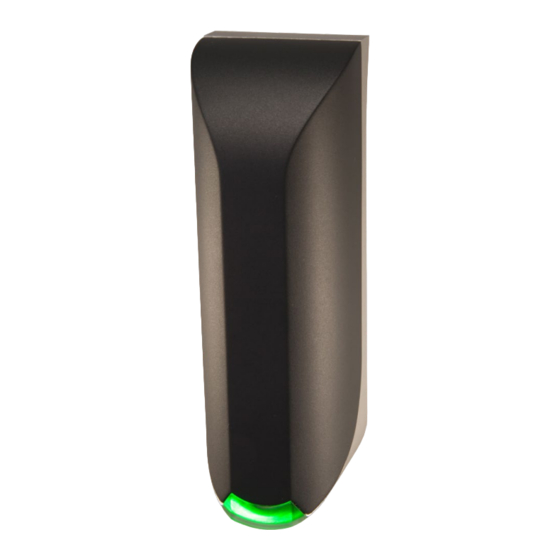
The uPASS Access offers identification up to 2 meter (6 feet) using the latest UHF technology. The uPASS Access includes a RS485 interface, a wiegand/magstripe and a RF-modulation interface. The uPASS Access can also be connected to NEDAP AEOS access control hardware such as the AP1001, using the RF-modulation interface. -
Page 5: Tag Security
(theoretically) cannot be cross-copied. This TID based anti-cloning mechanism is not considered to be a strong protection. NEDAP UHF tags support a locked serialized TID and the uPASS Access reader can be configured to read the TID data field. -
Page 6: Installation
The cable shield shall be connected with safety ground and the metal case of the external device(s). · To be sure of safety, do not modify or add anything to the uPASS Access other than mentioned in this installation guide or indicated by NEDAP N.V. - Page 7 Install the uPASS Access reader onto the base-plate. Feed the cable through the cable entry hole. Important note: minimum bending radius 30mm. Attach the top of the uPASS Access onto the base-plate. Fix the assembly using the screw on the bottom.
-
Page 8: Connections
Access 3 CONNECTIONS The uPASS Access is supplied with a 5 meter shielded cable pigtail with 12 multi-color wires. (15 feet) Power supply 12 - 24VDC. Power supply 0VDC, DC-Ground. BLACK RS485 A- BROWN RS485 A+ GREEN Data-0 / Clock... -
Page 9: Power Supply
Make sure your computer is connected to the internet. The driver should install automatically via Windows update when the uPASS Access reader is connected to your PC via the USB cable. Follow the driver installation wizard. If you do not see the Windows update pop-up, you can manually install the driver. To manually install, you need to go to FTDI’s website at... -
Page 10: Wiegand / Magstripe
WIEGAND / MAGSTRIPE The wiegand interface connections also support magstripe. NEDAP UHF Wiegand tags will generate a wiegand message on the interface. NEDAP UHF Magstripe tags will generate a magstripe message on the interface. Other UHF tags will not generate a message on this interface, unless the 'Extra output' settings are used! The wiegand/magstripe output format is determined by the programmed format of the tag. -
Page 11: Led Control
The shield shall be connected to the metal case of the external device. 3.5 NEDAP ANTENNA INTERFACE The Nedap antenna interface is used to connect the uPASS Access to NEDAP AEOS access control hardware such as the AP1001. Instead of proximity antenna the uPASS Access can be connected. -
Page 12: Uhf Frequencies
4 UHF FREQUENCIES 4.1 RADIO REGULATIONS The uPASS Access reader operates on the 860 – 960 MHz band. Regulations in this band are not standardized world-wide. Generally the regulations can be divided into several regions. Per region a specific frequency band is available. This frequency band is divided into frequency channels. If local radio regulations require frequency hopping (FHSS), then the uPASS Access automatically selects and uses the available channels. -
Page 13: Reader Configuration
By default the reader is configured to select ANY TAG and read its EPC number. Select NEDAP to read only Nedap tags. NEDAP DUAL-ID (introduced in firmware version 2.29) enables the uPASS to search for Nedap vehicle-id tags. When a vehicle-id tag is found, the uPASS searches for driver-id tags. -
Page 14: Decode Nedap Xs
Enable decode Nedap XS formatted tags. Introduced in firmware version 2.54. Figure 8: Output settings By default the data on NEDAP XS formatted tags will be transmitted to the TRANSIT compatible processor or the the NEDAP antenna modulation interface. In this case the UPASS will not perform any decoding. -
Page 15: Relay / Timing
The 'Vehicle hold time' setting is the time, after a vehicle-id tags has been found, for which the reader will search for driver-id tags. This setting is only used in the NEDAP DUAL-ID mode. Introduced in firmware version 2.29. The (random) RF off time parameter can be used to enable time sharing between multiple readers on the same frequency. -
Page 16: Expert Settings
'Enable vehicle id-events' allows enabling or disabling the id-event messages for vehicle-ids. This may be useful in combination with the NEDAP DUAL-ID mode and an access control panel that does not support the dual-id feature. -
Page 17: Extra Output
Access 5.3.3 EXTRA OUTPUT Optionally enable wiegand or magstripe output for tags that are not programmed by Nedap in a wiegand, magstripe or nedap-xs format. This feature is introduced in firmware version 2.13 or newer. 'Protocol': Disabled Do not use the additional output feature. -
Page 18: Frequency
Access 5.3.4 FREQUENCY Here is shown the reader's operating frequency region. Only for systems that do not use frequency hopping (e.g. in Europe): You can select a frequency channel within the available frequency band. Figure 15: Frequency 5.3.5 READ RANGE Enable the squelch to reduce the read range. -
Page 19: Atechnical Specifications
Relative humidity 10 .. 93 % non condensing Identification range Up to 2 meters (Line Off Site) With passive NEDAP UHF tags (6 feet) Power supply 12 … 24VDC ±10% linear power supply Current consumption 1A @ 12VDC, 0.5A @ 24VDC...
Need help?
Do you have a question about the uPASS Access and is the answer not in the manual?
Questions and answers