Table of Contents
Advertisement
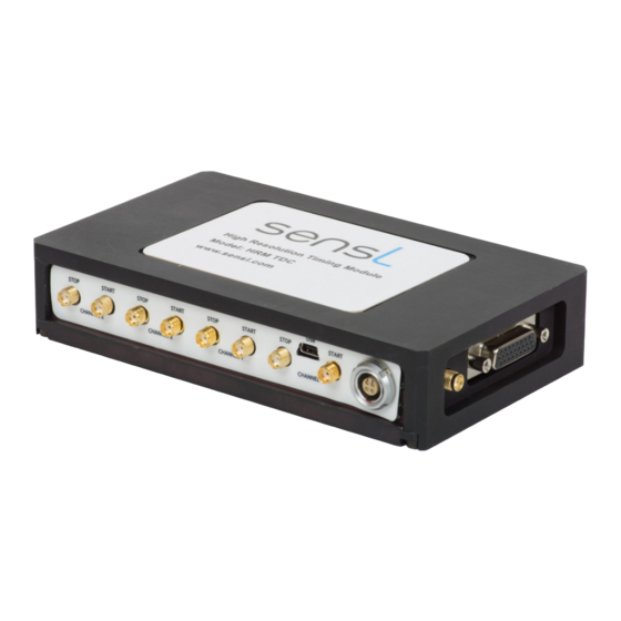
HRM-TDC
USER MANUAL
High Resolution Time-to-Digital Converter Module
Document Overview
This document provides the user with a comprehensive
description of the hardware and software of the HRM-
TDC module, including system description, the various
timing modes, software GUI and DLL drivers. The
document is split up into the following sections:
GETTING STARTED
This section provides instructions for unpacking the HRM-TDC and a brief overview.
SYSTEM DESCRIPTION
This section gives a description of the system hardware, the various ports and communication channels, the internal
processor, and the specific timing features.
SENSL INTEGRATED ENVIRONMENT (SIE)
The SIE is a user interface for setting up and controlling the HRM-TDC module. While the interface provides an
extensive range of operating modes and measurement processes, including graphical presentation, it does not fully
cover all features available in the HRM-TDC module. This section of the User Manual includes instructions for the
installation of the necessary software, and detailed description of each part of the SIE and how to set up and use it.
APPENDIX
The HRM-TDC DLL provides a set of functions that will allow full control of the HRM-TDC for all features. For
complex experiments that require control beyond the scope of the SIE, it is expected that the user will write their own
real-time application utilizing the various functions in this DLL. The Appendix of the User Manual covers Registers,
low level DLL functions, high level DLL functions, DLL error reporting and examples, as well as help and examples
for resolving time-tag values,an explanation of the correlation function used and the Labview drivers provided.
SensL © 2011
1
Advertisement
Table of Contents

Subscribe to Our Youtube Channel
Summary of Contents for sensl HRM-TDC
-
Page 1: Document Overview
APPENDIX The HRM-TDC DLL provides a set of functions that will allow full control of the HRM-TDC for all features. For complex experiments that require control beyond the scope of the SIE, it is expected that the user will write their own real-time application utilizing the various functions in this DLL. -
Page 2: Table Of Contents
Time-Bin and Time-Tag Controller ....................11 Data Router Module ........................11 Address Router Module ........................ 11 Dual Port Memory Arbiter ......................11 HRM-TDC Specific Feature Overview ....................12 HISTOGRAM ..........................13 FIFO ............................. 13 Histogram – Single-stop (“TCSPC” MODE) .................... 14 Histogram –... - Page 3 “FIFO – Time Tagging” (FIFO – Multi-stop) ..................26 Correlation ............................ 30 Appendix ..............................32 HRM-TDC Registers and Low Level DLL Functions ................32 Initialization Low Level Drivers ....................... 32 ARR – Address Route Register ..................... 33 DRR – Data Route Register ......................35 LAL, LAH –...
- Page 4 Resolving Free Running FIFO Time-Tag Values ..................66 Free Running Algorithm Explained ....................66 Resync Algorithm Explained ......................68 Correlation Function Algorithm ....................... 70 Labview Driver details ..........................71 HRM-TDC LabView Driver VI List ....................71 Sample LabView Application ......................84 SensL © 2011 SensL © 2011...
-
Page 5: Glossary
SensL Integrated Environment - the GUI that runs on the SensL DLL and provides an example SIE - program allowing the user to make measurements with the HRM-TDC. Least Significant Bit: The right most bit in a binary integer, and in the case of the HRM-TDC LSB - it determines the minimum timing resolution possible. -
Page 6: Getting Started
Liquids should not be spilled on or into the module. SYSTEM INSTALLATION PROCEDURES For software driver and SensL Integrated Environment installation instructions see the SIE User Guide on page 18 of this document. Please follow the instructions carefully and ensure you have installed the QuickUSB drivers as instructed. -
Page 7: Specifications
Number depends on USB capability of PC I/O control 16 fully programmable I/O ports Software SensL Integrated Environment (SIE) and DLL drivers PC Interface High speed USB 2.0 * Useful count rate is maximum count rate without loss of greater than 50% SensL ©... -
Page 8: Signal Inputs And Outputs
Channel 2 Stop Input (SMA LVTTL*) Channel 3 Start Input (SMA LVTTL*) Channel 3 Stop Input (SMA LVTTL*) USB connector LEMO power supply connector (for SensL PSU use only) 26-way I/O port connector Programmable Clock output (SMA LVTTL 50W) * 5V TTL tolerant... -
Page 9: Hrm-Tdc System Description
High Speed USB 2.0 Interface The USB interface is used to command/configure the HRM-TDC as well as download, in real-time, timing data to the host computer. This USB interface implements high speed USB 2.0 protocol allowing real time continuous logging of timing data up to rates of 4.5MHz without data loss. -
Page 10: 16-Bit General Purpose I/O Port
This module is responsible for receiving a set of commands from the host computer and controlling the system accordingly. HRM-TDC is a fully programmable system with a wide range of parameters that can be user defined. The Command Interpreter is responsible for setting these parameters and starting the execution of a particular task. -
Page 11: Dma To Usb Fast Transfer Interface
HRM-TDC USER MANUAL > Hrm-tdc System Description > System Processor And Controller Detailed Description DMA to USB Fast Transfer Interface The system memory is dual ported between the USB and the Time-Bin/Time-Tag controller. This module controls the reading of data from memory to the USB interface by means of high speed DMA block transfers. The Command Interpreter initializes this module with a start address and block data count. -
Page 12: Hrm-Tdc Specific Feature Overview
HRM-TDC SPECIFIC FEATURE OVERVIEW The flexibility of the HRM-TDC allows it to be used in a variety of modes. The following are examples of how the SIE software utilizes the START and STOP signals in different ways to cater for different applications. -
Page 13: Histogram
HRM-TDC USER MANUAL > Hrm-tdc System Description > Hrm-tdc Specific Feature Overview HISTOGRAM Histogram modes use consecutive memory locations to store counts that represent points on a graph. These memory locations or time bins are incremented based on the value of a time measurement. Each memory location represents a time range equal to the resolution of the timer. -
Page 14: Histogram - Single-Stop ("Tcspc" Mode)
HRM-TDC USER MANUAL > Hrm-tdc System Description > Histogram – Single-stop (“tcspc” Mode) HISTOGRAM – SINGLE-STOP (“TCSPC” MODE) Fig.1c Figure 5 Histogram modes use consecutive memory locations to store counts that represent successive timing values (Fig.5a). These memory locations or “time bins” are incremented based on the result of a time measurement between a START and the first STOP received. -
Page 15: Histogram - Multi-Stop ("Multiscaler/Counter")
HRM-TDC USER MANUAL > Hrm-tdc System Description > Histogram – Multi-stop (“multiscaler/counter”) HISTOGRAM – MULTI-STOP (“MULTISCALER/COUNTER”) Fig.2b Figure 6 In this mode, multiple STOP events following a single START event are recorded and their corresponding time bins in the histogram incremented (Fig.6a). The following START input will reset the timer and the following STOP events will be again recorded until another START is received. -
Page 16: Fifo - Single-Stop ("Tcspc - With Macro-Time")
HRM-TDC USER MANUAL > Hrm-tdc System Description > Fifo – Single-stop (“tcspc - With Macro-time”) FIFO – SINGLE-STOP (“TCSPC - WITH MACRO-TIME”) Fig.3c Fig.3d Figure 7 FIFO modes continually record the timing of events and save the results in consecutive locations in memory as shown in Fig.7a. -
Page 17: Fifo - Multi-Stop ("Fifo - Time Tagging")
HRM-TDC USER MANUAL > Hrm-tdc System Description > Fifo – Multi-stop (“fifo - Time Tagging”) FIFO – MULTI-STOP (“FIFO - TIME TAGGING”) Fig.4b Fig.4c Figure 8 In this mode the process is started with a single START pulse. The module will then fill the memory with time tags defining the time of each STOP event with relation to the initial single START pulse. -
Page 18: Sensl Integrated Environment (Sie)
> Sensl Integrated Environment (sie) > System Requirements SensL Integrated Environment (SIE) The SIE is a user interface for setting up and controlling the HRM-TDC module. While the interface provides an extensive range of operating modes and measurement processes, including graphical presentation, it does not fully cover all features available in the HRM-TDC module. -
Page 19: Using The Sensl Integrated Environment (Sie)
Main Page When the SIE software is launched it will search the USB for available HRM-TDC modules and initialize them ready for use. Once this has been carried out the main SIE page will appear as shown in Figure 9. A list of available devices will be shown. -
Page 20: Histogram -Tcspc" (Histogram Single-Stop)
> Sensl Integrated Environment (sie) > Using The Sensl Integrated Environment (sie) Updating the FPGA should only be carried out if you are instructed to do so by SensL. This procedure requires a valid RPD file as provided by SensL. - Page 21 HRM-TDC USER MANUAL > Sensl Integrated Environment (sie) > Using The Sensl Integrated Environment (sie) Reverse Plot Due to the method of TCSPC measurement, where the start and stop events are reversed, it is sometimes useful to plot the curves with the TIME axis reversed. Selecting this option will reverse the time axis for the plot.
-
Page 22: Histogram - Multi-Scaler" (Histogram Multi-Stop)
HRM-TDC USER MANUAL > Sensl Integrated Environment (sie) > Using The Sensl Integrated Environment (sie) Graphical Presentation Once the configuration is selected, the configuration page can be removed by clicking on the X tab to display the graph section only (see Figure 12). -
Page 23: Fifo - Tcspc With Macro Time" (Fifo Single-Stop)
The size of the configuration and graph area can be adjusted by dragging the partition to suite. This page is a graphical demonstration of the TCSPC with MACRO time feature of the HRM-TDC module. The HRM- TDC allows the user to carry out TCSPC and save time tags. These time tags consist of the TCSPC measurement plus a MACRO time defining at what time during the experiment the measurement was made. - Page 24 HRM-TDC USER MANUAL > Sensl Integrated Environment (sie) > Using The Sensl Integrated Environment (sie) Channel Enable and Edge Selection These check boxes allow the individual channels to be enabled/disabled and the START/STOP inputs sensitivity to be specified. Note: Press Apply changes button to set your selected configuration.
- Page 25 HRM-TDC USER MANUAL > Sensl Integrated Environment (sie) > Using The Sensl Integrated Environment (sie) was set o trigger on the HI-LO transition. As can be seen in Fig 14, the time-tags are repeating every 200 counts of the MACRO time. As the resolution of the MACRO time was set to 5ns, this represents a repetition rate of 1ms (200 x 5 ns).
-
Page 26: Fifo - Time Tagging" (Fifo - Multi-Stop)
HRM-TDC USER MANUAL > Sensl Integrated Environment (sie) > Using The Sensl Integrated Environment (sie) Figure 14 Typical output data from streaming TCSPC Time Tags “FIFO – Time Tagging” (FIFO – Multi-stop) This page is used to continuously stream event time tags, as shown in Fig. 15. This mode offers 2 methods that are selected by the value of the programmable clock. - Page 27 HRM-TDC USER MANUAL > Sensl Integrated Environment (sie) > Using The Sensl Integrated Environment (sie) Resync: Using this method, the user must feed the programmable clock output to the Start input of any channel being used. Once the configuration is selected, the user can start the module recording. The module will wait for the first Start pulse and then start recording every stop event until the recording time is reached, the maximum event count is reached or the process is manually stopped.
- Page 28 HRM-TDC USER MANUAL > Sensl Integrated Environment (sie) > Using The Sensl Integrated Environment (sie) Recording Length The recording length should be set to the desired period over which the TCSPC measurements are to be taken. Maximum Event Count This defines the maximum number of events to be stored before recording stops. This value is used to ensure the storage data size does not exceed the capacity of the system.
- Page 29 HRM-TDC USER MANUAL > Sensl Integrated Environment (sie) > Using The Sensl Integrated Environment (sie) time. The time tag for this mode consists of 2 x 32-bit words. The first word is a micro time that has a resolution down to 27ps.
-
Page 30: Correlation
HRM-TDC USER MANUAL > Sensl Integrated Environment (sie) > Using The Sensl Integrated Environment (sie) Correlation The Correlation feature allows the user to carry out cross and auto correlation on FIFO-TCSPC streams for both the TCSPC values and the MACRO times. The correlation screen is shown in Fig. 17. - Page 31 HRM-TDC USER MANUAL > Sensl Integrated Environment (sie) > Using The Sensl Integrated Environment (sie) Figure 17 SIE Correlation screen SensL © 2011 SensL © 2011...
-
Page 32: Appendix
HRM-TDC REGISTERS AND LOW LEVEL DLL FUNCTIONS The control and setup of the HRM-TDC is carried out by a series of commands to a set of configuration registers within the module. To simplify the control of these registers, a set of low level drivers, in a DLL, is available. The low level drivers will return an HRM_STATUS of value HRM_OK or HRM_ERROR. -
Page 33: Arr - Address Route Register
On receipt of a time-tag the system outputs the time-tag as an address and then increments that location (time-bin). In the HRM-TDC system further data bits are included in the address selection to allow multiple curve plotting based on multiple channel inputs and discrete inputs for X, Y array plotting. - Page 34 IODATA(0) and the line counter is incremented by clock inputs to IODATA(1). If these bits are routed to the address lines then the user can command the HRM-TDC module to move from one curve to the next by clocking the IODAT(0) and IOADAT(1) lines.
-
Page 35: Drr - Data Route Register
DRR – Data Route Register Register Description When the HRM-TDC system is in time-tag mode it will continually save time-stamps to memory. Each time-stamp will always be 32-bits, however the format of the time-stamp is programmable using the DRR. To allow maximum flexibility the DRR register can define any ‘Data Option Bit’... -
Page 36: Lal, Lah - Load Address Lo/Hi Register
HRM-TDC USER MANUAL > Appendix > Hrm-tdc Registers And Low Level Dll Functions TagData This is the time-tag data as received by the Pico-Second Timing Interface. Bits 23,24 define the channel the time-tag was received on – 00, 01, 10 or 11. The bits 22 down to 0 define the time with bit 0 being the LSB (LSB = 26.9851ps). -
Page 37: Lfl, Lfh - Load Fill Value Lo/Hi Register
Register Description The user can command the HRM-TDC module to fill a range of memory with a given value. The value used for this command is defined using these 2 commands. The initialization value is a 32-bit value. The most significant 16 bits is defined by LFH and the least significant 16 bits is defined bits LFL. -
Page 38: Mbr - Mode Bits Register
32-bit address to set UAH, UAL to. MBR – Mode Bits Register Register Description This register defines a number of settings for the HRM-TDC module as follows: Rmd Mem Nu Size Md[2..0] These bits define in which mode the HRM-TDC module will operate. -
Page 39: Esr - Edge Sensitivity Register
HRM-TDC USER MANUAL > Appendix > Hrm-tdc Registers And Low Level Dll Functions and BCL is disabled. This bit, when set to ‘1’, will start the high speed USB memory or time-tag transfer processor. Taking this bit to ‘0’, at any time, will immediately put the processor into reset. -
Page 40: Rrr - Routing Reset Register
HRM-TDC USER MANUAL > Appendix > Hrm-tdc Registers And Low Level Dll Functions Driver - HRM_SetEdgeSensitivityRegister HRM_STATUS WINAPI HRM_SetEdgeSensitivityRegister(HANDLE handle, USHORT esrData) handle: HRM-TDC module handle esrData: 16-bit value to write to the ESR. RRR – Routing Reset Register Register Description... -
Page 41: Fsr - Frequency Select Register
Register Description The 16-bit I/O signals of the HRM-TDC can be programmed to be inputs or outputs. The value of this register defines the direction of each I/O bit. Setting a bit in this register to ‘1’ will program the corresponding I/O bit as an output. -
Page 42: Bcl, Bch - Bin Count Lo/Hi Register
HRM-TDC USER MANUAL > Appendix > Hrm-tdc Registers And Low Level Dll Functions Driver - HRM_SetIOValueRegister HRM_STATUS WINAPI HRM_SetIOValueRegister(HANDLE handle, USHORT iovrData) handle: HRM-TDC module handle iovrData: Value to write to the IVR BCL, BCH – Bin Count LO/HI Register Register Description These registers define the maximum number bins that can occur during the period of the TCSPC clock. -
Page 43: Hrs, Hrm-Tdc Status Register
HRS, HRM-TDC Status Register Register Description Reading this register will report the status of the HRM-TDC module as follows: If set to ‘1’, the TCSPC time-tag/time-bin processor is active. If set to ‘1’, the memory high-speed data transfer processor to the USB port will be active. -
Page 44: Pcr - Product Code Register
Reading from this register will report the PRODUCT code. The LS byte will report the product ID and the MS byte defines any variants from the standard product. For a standard HRM-TDC module this value should read 0x0001. Low Level Driver... -
Page 45: Wch - Write Count Hi Register
HRM-TDC USER MANUAL > Appendix > Hrm-tdc Registers And Low Level Dll Functions Driver - HRM_GetModuleIDRegister HRM_STATUS WINAPI HRM_GetModuleIDRegister(HANDLE handle, BYTE *midData) handle: HRM-TDC module handle midData: Pointer for saving text string of the HRM-TDC module ID WCH – Write Count HI Register... -
Page 46: Non-Register Specific Low Level Drivers
HRM-TDC USER MANUAL > Appendix > Hrm-tdc Registers And Low Level Dll Functions Non-Register Specific Low Level Drivers Driver - HRM_InitMemory HRM_STATUS WINAPI HRM_InitMemory( HANDLE handle, ULONG addr, ULONG len, ULONG fillData) Fill a block of memory with a specific bit pattern. - Page 47 HRM-TDC USER MANUAL > Appendix > Hrm-tdc Registers And Low Level Dll Functions Driver - HRM_GetMemorySize HRM_STATUS WINAPI HRM_GetMemorySize( HANDLE handle, ULONG *size) Gets the memory size of the module in bytes. handle: HRM-TDC module handle size: Pointer to location for storing number of memory bytes.
-
Page 48: High Level Dll Functions
> Appendix > High Level Dll Functions HIGH LEVEL DLL FUNCTIONS The HRM-TDC DLL (HRMTimeAPI.DLL) contains a set of high level drivers designed to allow the user to easily stream date from the module to memory or file. These drivers are as follows:... - Page 49 USHORT macrolsb, ULONG *recordedbytes) Stream FIFO date to memory buffer (TCSPC with MACRO mode). handle: HRM-TDC module handle buf: Pointer to memory buffer bufsize: Memory buffer size in bytes. Recording stops if this is reached. recordinglength: Time in msec to stream data to buffer (while buffer not full)
- Page 50 ULONG esr, USHORT microlsb) Stream FIFO date to file (FIFO Time-Tagging mode). handle: HRM-TDC module handle outfname: File name for storing data recordinglength: Time in msec to stream data to file esr: Module ESR register value for defining channels and edge sensitivity microlsb: Micro resolution.
- Page 51 USHORT microlsb, ULONG *recordedbytes) Stream FIFO date to memory buffer (FIFO Time-Tagging mode). handle: HRM-TDC module handle buf: Pointer to memory buffer bufsize: Memory buffer size in bytes. Recording stops if this is reached. recordinglength: Time in msec to stream data to buffer (while buffer not full)
- Page 52 Storage location for channel ID (0, 1, 2 or 3) micro: Storage location for micro time in picoseconds macro: Storage location for macro time in nanoseconds HRM_STATUS returned equal to HRM_OK if success SensL © 2011 SensL © 2011...
- Page 53 *corr Carries out a correlation algorithm on two sets of Time Bins. handle: HRM-TDC module handle Pointer to an array of time bin values Number of bins in x array Pointer to an array of time bin values Number of bins in y array...
- Page 54 Starts running the FIFO TCSPC mode. Once this has been executed the function HRM_GetFifoData can be used to continuously download the data. handle: HRM-TDC module handle ESRreg: Module ESR register value for defining channels and edge sensitivity microbits: Number of micro TCSPC bits in time-tag (max value = 23) microlsb: TCSPC resolution.
- Page 55 FIFO_TCSPC, FIFO_FREE_RUNNING or FIFO_RESYNC microBits: Number of micro bits. Only applicable for FIFO_TCSPC mode. rawFile: Name of RAW binary file csvFile: Name of file to store TEXT formatted data HRM_STATUS returned equal to HRM_OK if success SensL © 2011 SensL © 2011...
-
Page 56: Dll Error Reporting
:Could not open O/P file HRM_INV_PARAMETER :Invalid function parameter HRM_WRITE_COMMAND :Error writing command HRM_READ_COMMAND :Error reading command HRM_READ_DATA :Error reading data block HRM_FIFO_OVERFLOW :FIFO has overflowed HRM_BUFFER_FULL :Memory buffer full HRM_TIMEOUT :Timeout error HRM_NO_MODULE_FOUND :Could not detect module SensL © 2011 SensL © 2011... -
Page 57: Dll Application Examples
Num; Sdoub gapT, Tot, mac, mic; error = HRM_OK; pMAC = 0; pMIC = 0; = NULL; = NULL; Detect the number of HRM-TDC modules HRM_RefreshConnectedModuleList(); moduleCount = HRM_GetConnectedModuleCount(); SensL © 2011 SensL © 2011... - Page 58 If an argument then read the TCSPC time-tags, get the macro and micro values in ns and ps and put to the TXT file for(Num=1, flag=1; flag && error == HRM_OK && argc != 1; Num++) if((fread(ttag, 4, 1, fi)) == 0) flag = 0; SensL © 2011 SensL © 2011...
- Page 59 Error code = %d”, error); Histogram Example Description The following example sets up the module in TCSPC or Multi-scalar Histogram mode. This console-based application allows input parameters to define setup information as follows: SensL © 2011 SensL © 2011...
- Page 60 This automatically splits the memory into 4 blocks, 1 for each channel. The histogram for channel 0 will start at 32-word address 0. The histogram for channel 1 will start at 32-word address 0x80000. The histogram SensL © 2011 SensL © 2011...
- Page 61 Sbyte *argv[]) HRM_STATUS error; Uword tcspc, delay, chann; Uword period, clock; Ulong moduleCount, offset, range, i; HANDLE hdl[10]; FILE *fl; Initialise variables and clear error report error = HRM_OK; tcspc = 0; SensL © 2011 SensL © 2011...
- Page 62 = (Uword)((clock << 8) | clock); 1. Set the flag for TCSPC or MULTI-SCALAR mode 2. Read in the time in ms for running the histogram. 3. Form the 4 channel edge enables based on the input parameter. SensL © 2011 SensL © 2011...
- Page 63 |= 0x0900; if(argv[2][2] == ‘1’) chann |= 0x0090; if(argv[2][3] == ‘1’) chann |= 0x0009; Detect the number of HRM-TDC modules if(error == HRM_OK) HRM_RefreshConnectedModuleList(); moduleCount = (Ulong)HRM_GetConnectedModuleCount(); If a module is present connect to the first module. If no module, set error and reason in last error report.
- Page 64 For each channel read all the time-bins from 20ns before to 20ns after the 1/2 clock cycle and save then in the file. for(i=0; i!=range && error == HRM_OK; i++) fprintf(fl, “%ld,%ld,%ld,%ld\n”, buffer[i+CH0_ADDR+offset], buffer[i+CH1_ADDR+offset], buffer[i+CH2_ADDR+offset], buffer[i+CH3_ADDR+offset]); SensL © 2011 SensL © 2011...
- Page 65 HRM-TDC USER MANUAL > Appendix > Dll Application Examples Close the file and print error code if failed. if(fl) fclose(fl); if(error == HRM_OK) printf(“Done”); else error = HRM_GetLastError(HRM_OK); printf(“Failed: Error code = %d”, error); SensL © 2011 SensL © 2011...
-
Page 66: Resolving Free Running Fifo Time-Tag Values
If previous value (pMICRO) is greater than current (cMACRO) then counter has rolled over so dMICRO = 0x510000 – pMICRO + cMICRO Calculate total time between time-tags dTIME dTIME = (nMICRO x rMICRO) + (dMICRO x 26.9851) ps SensL © 2011 SensL © 2011... - Page 67 > pMICRO) dMICRO = (cMICRO - pMICRO) * 26.9851; else dMICRO = (cMICRO + 0x510000 – pMICRO) * 26.9851; Calculate the change in time from previous to current time-tag dTIME = dMICRO + dMACRO; SensL © 2011 SensL © 2011...
-
Page 68: Resync Algorithm Explained
If MACRO is near end of boundary and MACRO FrameNo = FrameNo + 1; is small the ROLLOVER has already occurred. Now calculate the time in picoseconds Time = (FrameNo x 4000000) + (MICRO x 26.9851) SensL © 2011 SensL © 2011... - Page 69 < 60 && MicroValue > 100000) MACRO--; if(FRACT > 110 && MicroValue < 40000) MACRO++; Calculate the time in picoseconds. = (double)MACRO; = (double)MicroValue; dTIME = (dv1 * 4000000) + (dv2 * 26.9851); SensL © 2011 SensL © 2011...
-
Page 70: Correlation Function Algorithm
-1 <= r(d) <= 1, the bounds indicating maximum correlation and 0 indicating no correlation. A high negative correlation indicates a high correlation but of the inverse of one of the series. SensL © 2011 SensL © 2011... -
Page 71: Labview Driver Details
> Appendix > Labview Driver Details LABVIEW DRIVER DETAILS The HRM-TDC Labview driver has been designed to allow the construction of a wide variety of custom applications based on the HRM-TDC module. The library contains VI wrappers for all functions defined in the HRM-TDC API DLL. - Page 72 Connected module count Returns the number of connected modules detected by the previous HRM_ RefreshConnectedModuleList call HRM_GetConnectedModuleList.vi Handle list Numeric Holds the list of handles for the connected moduled detected by the previous HRM_RefreshConnectedModuleList call SensL © 2011 SensL © 2011...
- Page 73 Address routing data Numeric Data to be written to the address route register Handle Module handle HRM_SetDataRouteRegister.vi Handle Module handle Data route routing data Numeric Data to be written to the Data Route Register SensL © 2011 SensL © 2011...
- Page 74 > Appendix > Labview Driver Details HRM_SetAddressRegister.vi Address Data to be written to the Address Register Handle Module handle HRM_SetFillValueRegister.vi Handle Module handle Fill value Memory fill value HRM_SetUSBAddressRegister.vi Handle Module handle USB Address USB block transfer address SensL © 2011 SensL © 2011...
- Page 75 > Appendix > Labview Driver Details HRM_SetModeBitsRegister.vi Handle Module handle Mode bits data Mode bits data HRM_SetEdgeSensitivityRegister.vi Handle Module handle Edge sensitivity Edge sensitivity data HRM_SetRoutingResetRegister.vi Handle Module handle Routing reset Routing reset data SensL © 2011 SensL © 2011...
- Page 76 USER MANUAL > Appendix > Labview Driver Details HRM_SetMemoryCountRegister.vi Handle Module handle Memory count Memory count HRM_SetUSBCountRegister.vi Handle Module handle USB count USB count data HRM_SetFrequencySelectionRegister.vi Handle Module handle Frequency selection Frequency selection data SensL © 2011 SensL © 2011...
- Page 77 USER MANUAL > Appendix > Labview Driver Details HRM_SetIODirectionRegister.vi Handle Module handle IO direction GPIO direction data HRM_SetIOValueRegister.vi Handle Module handle IO value IO value data HRM_SetBinCountRegister.vi Handle Module handle Bin Count Bin Count SensL © 2011 SensL © 2011...
- Page 78 HRM-TDC USER MANUAL > Appendix > Labview Driver Details HRM_GetStatusRegister.vi Handle Module handle Status Status data HRM_GetSoftwareRevisionRegister.vi Handle Module handle FPGA revision FPGA revision HRM_GetWriteCountRegister.vi Handle Module handle Write count Write count SensL © 2011 SensL © 2011...
- Page 79 Handle Module handle Start address Start address Length Block length Fill data Fill data HRM_ReadMemory.vi Handle Module handle Mode mask Mode bits mask Start address Read start address Length Read block size Buffer Read buffer Numeric SensL © 2011 SensL © 2011...
- Page 80 USER MANUAL > Appendix > Labview Driver Details HRM_ReadFIFOMemory.vi Handle Module handle Mode mask Mode bits mask Start address Read start address Length Read block size Buf Read buffer Numeric HRM_RequestStop.vi Handle Module handle SensL © 2011 SensL © 2011...
- Page 81 Recording length Recording time in ms Micro bits Number of microtime bits Micro LSB Microtime least significant bit Macro bits Number of macrotime bits Macro LSB Macrotime least significant bit File name Output filename Edge selection Edge selection data SensL © 2011 SensL © 2011...
- Page 82 Buffer size Read buffer size Recording length Recording time in ms Edge selection Edge selection data Microtime lsb Microtime least significant bit Number of recorded bytes Number of recorded bytes Buffer Numeric Read buffer SensL © 2011 SensL © 2011...
- Page 83 Edge selection Edge selection data Microtime lsb Microtime least significant bit HRM_ConvertRawContTTagsFile2CSV.vi Input file Input (raw) filename Output file Output (CSV) filename Microtime lsb Microtime least significant bit (must match the value used for the HRM_StramTimeTags2File call) SensL © 2011 SensL © 2011...
-
Page 84: Sample Labview Application
HRM-TDC USER MANUAL > Appendix > Labview Driver Details Sample LabView Application Test_TCSPC.vi This is a sample application demonstrating the TCSPC stream-to-file functionality. SensL © 2011 SensL © 2011... - Page 85 > Appendix > Labview Driver Details www.sensl.com sales@sensl.com +353 21 240 7110 (International) +1 650 641 3278 (North America) All specifications are subject to change without notice Rev. 3.0, December 2017 SensL © 2011 SensL © 2011 SensL © 2011...
Need help?
Do you have a question about the HRM-TDC and is the answer not in the manual?
Questions and answers