Table of Contents
Advertisement
Advertisement
Table of Contents

Subscribe to Our Youtube Channel
Summary of Contents for Sailor SC4000 Iridium
- Page 1 TECHNICAL MANUAL SAILOR SC4000 IRIDIUM...
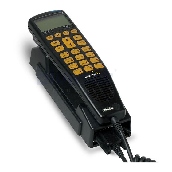
- Page 2 Introduction Your Iridium equipment is a modular system that consists of a transceiver unit, control handset unit, antenna unit and an optional analogue PSTN telephone/PABX. You can make and receive voice calls on the control handset and the analogue PSTN telephone. You can connect up to four handsets and one analogue PSTN telephone or PBX switchboard to the system.
-
Page 3: Table Of Contents
IRIDIUM Installation Contents Technical Specifications ........................... 2 Installation ................................4 Version Overview ..............................4 Configuration of Single-Channel Unit ........................4 Cable Overview ..............................5 2.3.1 Scanbus Termination ............................6 Where to Place the Satellite Transceiver Box ..................... 7 How to Mount the Satellite Transceiver Box ......................7 How to Put on the Finishing Cover ........................ -
Page 4: Technical Specifications
Installation IRIDIUM 1 Technical Specifications Space Segment Satellites 66 (Plus 6 in-Orbit backup satellites) Orbital planes Orbit height 780 kilometres Inclination of the orbital planes 86.4 degrees Orbital period 100 minutes, 28 seconds Spot beams 48 per satellite Radio module Frequency Range 1616 MHz to 1626.5 MHz (L-Band) Duplexing Method... - Page 5 IRIDIUM Installation Power supply 10 – 32V DC AC (Optional) 110-230V AC (External adaptor) Consumption 25 W during communication 8 W Stand by Environmental Conditions Transceiver Operating temperature -10° C to +55° C Storage temperature -30° C to +70° C Antenna Temperature EME -35°...
-
Page 6: Version Overview
Installation IRIDIUM 2 Installation 2.1 Version Overview This manual covers the Transceiver Unit versions Mk2, Mk3 and Mk4. The version can easily be determined by looking at the area around the SIM card reader. 2.2 Configuration of Single-Channel Unit Iridium Antenna Unit Transceiver Unit... -
Page 7: Cable Overview
IRIDIUM Installation Cable 2 Cable Overview Phone Cable 1 Cable connector type: RJ 11 Scanbus Transceiver Description Cable: 9*0.22 mm shielded shield connected to ground phone1+ Cable connector type: 9 pole sub-d male phone1- Transceiver Description Handset Colour data+ white Twisted data- brown... -
Page 8: Scanbus Termination
Installation IRIDIUM Cable 5 2.3.1 Scanbus Termination Description of connections to T-connection H4196 The scanbus connecting the transceiver and the control (optional accessory) units, has to be terminated. Only the first and last unit on The wire terminal blocks are connected in parallel. the bus shall have the termination in ON position. - Page 9 IRIDIUM Installation When configuring a system only including a transceiver one control unit, it is needed to remove some of the default unit and one control unit, no changes in the default terminations. Below two examples of scanbus termination termination is needed. If the system includes more than is given, when the system includes several control units.
-
Page 10: Where To Place The Satellite Transceiver Box
Installation IRIDIUM First tighten three of the screws. The wall surface should 2.4 Where to Place the Satellite be plane. If there is a discrepancy in planeness exceeding Transceiver Box 1 mm, level the discrepancy up by shims or washers Mount the satellite transceiver box in a place where it is under the fourth screw before this is tightened. -
Page 11: How To Insert The Sim Card
IRIDIUM Installation Lift the SIM card holder so that the slot points upwards. Press hard on the spots shown in the picture below until a loud click is heard. Insert the SIM card in the slot. Make sure that the cut-off corner of the card is placed as shown in the picture. -
Page 12: Optional Sim Card Reader
Installation IRIDIUM 2.8 Optional SIM card Reader How to Remove the Finishing Cover Only direct accessible on Mk3 units produced from August You may need to dismount the satellite transceiver box 16, 2003. On older units the L-Band transceiver must be from the wall, e.g. -
Page 13: Installation Of The Antenna
IRIDIUM Installation The fitting in fig. 2 can be used at the top of a tube. Please 2.10 Installation of the Antenna note that it is necessary to mount the cable, and seal this One of the advantages of this equipment is the easy-to- connection securely before the antenna and fitting are handle, lightweight and rugged antenna. - Page 14 Installation IRIDIUM Precautions Inmarsat equipment In order to avoid interference or any other kind of The operating frequency bands of the iridium and Inmarsat disturbances from other systems on board, there are a systems are neighbours, and it is not in any way by any few precautions to take note of: technical solution possible to completely separate these bands.
-
Page 15: Analogue Telephone
IRIDIUM Installation The table below shows the distance to other Inmarsat equipment, with and without use of filter. Main Lobe Side Lobe Back-Lobe 9505 ISU Protection Distance (Metres) (Metres) (Metres) No Filter Inmarsat (Mini-M) No Filter Inmarsat (Std-M) No Filter Inmarsat A No Filter Inmarsat B... -
Page 16: Data Interface
Installation IRIDIUM Note: Some analogue phone line impedance may differ 2.13 External Ringer Interface from the commonly used standards. If the ringing volume The external ringer output pin in the Service/NMEA port is too low, the ringing voltage can be changed to gain can control an optional ringer or a lamp. - Page 17 IRIDIUM Installation 0514...
- Page 18 Installation IRIDIUM 0514...
-
Page 19: Spare Parts List
IRIDIUM Installation Appendix A Spare Parts List 81412000 82412000 83412000 Itemnumber Itemnumber Itemnumber Item Power cable 56.140 TNC/N adaptor 79.005 79.005 N.A. Coax cable with TNC male - N female N.A. 56.181* 56.181 ID kit 49.310 Fuse 45.669 Scanbus male 9p Sub-D 78.758 Scanbus female 9p Sub-D 78.765... - Page 20 Thrane & Thrane A/S info@thrane.com www.thrane.com • •...
Need help?
Do you have a question about the SC4000 Iridium and is the answer not in the manual?
Questions and answers