Advertisement
Available languages
Available languages
Quick Links
English
Palladiom Thermostat
P/N 043484 Rev. B
HQWT-T-HW
10/2017
24 – 36 V- 60 mA
Installation Instructions
IEC SELV / NEC
Class 2: 24 – 36 V- 60 mA
®
Please Read Before Installing
Contents
Thermostat
Sealed wallbox and color trim ring
Use sealed wallbox and
trim ring for all applications
except solid masonry or
poured concrete walls.
Removable terminal
Adapter and screws for metal wallbox
blocks
[metal wallbox (EBB-1-SQ) sold separately]
Use with metal wallbox
1
2
3
4
–
+
G
in solid masonry or
poured concrete walls.
Wallbox options
• For hollow walls that may have air movement in the wall cavity, use the sealed
wallbox included with thermostat.
• For solid masonry or poured concrete walls with no airflow, use a 2.75 in x 2.75 in
(70 mm x 70 mm) metal wallbox (e.g., EBB-1-SQ) with a minimum depth of 1.38 in
(35 mm).
– Single wallbox: Lutron model number EBB-1-SQ
– Pack of 15 wallboxes: Lutron model number EBB-15-SQ
• Bend back the top and bottom tabs on the metal wallbox before installing the
wallbox adapter.
• If running conduit to the wallbox, use a low-profile conduit connector with a
maximum height of 0.125 in (3 mm).
Important Notes
Codes: All wiring must be installed in accordance with all local and national
electrical codes.
Operating temperature: 32 °F to 104 °F (0 °C to 40 °C), 0% to 90% humidity,
non-condensing. Indoor use only.
Air circulation: The back of the thermostat that is mounted in the wall should not
be exposed to airflow or drafts, while the front exposed surface is intended to be
mounted in an area that is exposed to air that is representative of the space.
Cleaning: Clean with a damp cloth. Do NOT spray with water or any chemical
cleaning solutions.
Mounting
• Mount on a clean, dry, interior wall.
• Mount approximately 4 ft to 5 ft (1.2 m to 1.5 m) above the floor. Follow all local
and national codes.
• Mount on a wall without pipes, chimneys, or ducts.
• Mount on a wall with good visibility and control access.
• Do not mount on an exterior wall, close to a window, next to a door, or areas with
drafts.
• Do not mount in direct airflow from supply and return registers / grilles.
• Do not expose to water (e.g., drips or splashes) or mount in a damp area.
• Do not mount within 4 ft (1.2 m) of heating sources (e.g., direct sunlight, light bulbs,
etc.).
• Do not mount in areas with poor circulation (e.g., niches, alcoves, behind curtains,
or behind doors).
• Do not mount within 0.75 in (19 mm) of Palladiom keypads.
Note: If it is not possible to follow these guidelines, the use of an indoor remote
temperature sensor is recommended. For more details, see the installation
instructions included with the HomeWorks QS Palladiom HVAC controller.
Inside Wall
4 – 5 ft
(1.2 – 1.5 m)
Lutron Electronics Co., Inc.
7200 Suter Road, Coopersburg, PA 18036-1299 U.S.A.
Installation
1. Turn OFF power to the QS link.
WARNING: Shock Hazard. May result in serious injury or death.
Disconnect all power sources before installing or servicing unit.
2. Install the wallbox / adapter and wires.
a. Sealed wallbox
i. Cut a 2.75 x 2.75 in (70 x 70 mm) hole in the wall at the ideal thermostat
location. See Mounting section for more information.
ii. From the rear of the wallbox, firmly push the wires through the sealed
wire gaskets.
iii. Ensure that the arrows are pointing up and insert the wallbox into the hole.
Tighten the mounting screws.
iv. Snap the color trim ring to the sealed wallbox.
b. Metal wallbox (e.g., EBB-1-SQ) – already installed during construction
i. Ensure that a low-profile chase nipple was used and is 0.125 in (3 mm) or
less. If a low-profile chase nipple was not used, replace it with a low-profile
one. To prevent air flow, seal the gaps between the wires.
Seal
0.125 in (3 mm)
or less
ii. If the metal wallbox has top or bottom mounting tabs, bend them back
before installing the adapter.
iii. Screw the adapter to the metal wallbox using the two screws provided.
Lutron, HomeWorks, and Palladiom are trademarks of Lutron Electronics Co., Inc., registered in the U.S. and other countries. NEC is a registered trademark of the National Fire Protection Association, Quincy, Massachusetts.
©2017 Lutron Electronics Co., Inc.
3. Connect wires to the terminal blocks (supplied).
HVAC controller communication link*
Data Link
2
One shielded, twisted pair 18 AWG (1.0 mm
)
–: _
+: MUX
G: Common
IEC SELV / NECR Class 2
One 18 AWG (1.0 mm
2
)
HomeWorks QS
1
2
3
4
–
+
G
Palladiom thermostat
HomeWorks QS
Palladiom HVAC
1
2
3
4
controller**
1
2
3
4
QS link
Data Link
IEC SELV / NECR Class 2
One shielded, twisted pair
1: Common (Black)
22 AWG – 18 AWG
2: V+ (Red)
(0.25 mm
2
– 1.0 mm
3: MUX
Drain /
1
2
3
4
†
4: _
Shield
One or two 18 AWG
Two 12 AWG
OR
2
(1.0 mm
)
(2.5 mm
QS Link Wire Sizes
1
2
3
4
Length
Wire Gauge
Lutron Cable Part Number
Power (terminals 1 and 2)
2
1 pair 18 AWG (1.0 mm
)
GRX-CBL-346S (non-plenum)
< 500 ft (153 m)
GRX-PCBL-346S (plenum)
Data (terminals 3 and 4)
1 twisted, shielded pair 22 AWG
(0.5 mm
2
)
Power (terminals 1 and 2)
1 pair 12 AWG (4.0 mm
2
)
This will not fit in terminal. Connect
as shown above.
500 – 2000 ft
GRX-CBL-46L (non-plenum)
(153 – 610 m)
GRX-PCBL-46L (plenum)
Data (terminals 3 and 4)
1 twisted, shielded pair 22 AWG
2
(0.5 mm
)
4. Reattach the terminal blocks to the thermostat if they were removed during the
wiring process.
5. Snap the thermostat into the sealed wallbox or adapter.
6. Turn ON power to the QS link. The thermostat display will turn on.
* Not applicable for companion thermostats.
** Sold separately. For more information, see the HomeWorks QS Palladiom HVAC Solution spec
submittal at www.lutron.com/TechnicalDocumentLibrary/3691033.pdf
†
Do not connect the drain / shield wire to earth / ground or to the thermostat and do not allow it to
contact the grounded wallbox.
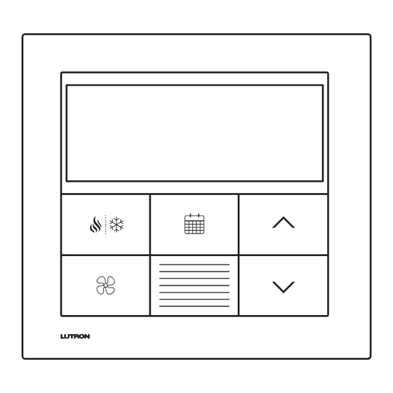
User Interface
Room temperature
1, 2
Heating mode
Display backlighting
Auto
System off
4
Auxiliary heat
On
5
mode
Auto
On
Cooling mode
1, 2
Auto
On
Only
AUTO
Aux
Heat On
Set
Fan mode
7
OFF
Cool On
High
Set
On
Auto
Medium
Low
Auto
Auto
On
On
Select system heat,
Dynamic Backlight
cool, only aux, auto,
Change fan
7
Management (DBM)
or off
mode
sensor location
1
Icons are animated when system is actively heating / cooling (when using SMC55-RESI).
2
Icons flash if system is temporarily delayed for HVAC equipment protection (when using SMC55-RESI).
3
Turns on when any button is pressed. Turns off after 10 seconds of inactivity (programmable). Dynamic
Backlight Management (DBM) automatically adjusts backlight intensity based on ambient lighting
conditions.
4
Room temperature, "OFF", and fan mode (when fan is running) are shown when system is off.
5
"Aux" indicates that auxiliary heat is running with the other heat stages. "Only Aux" indicates that auxiliary
heat is running without the other heat stages (emergency heat).
6
Indicates HVAC system timeclock event status.
2
)
7
Applicable modes are configurable via the HomeWorks QS software.
8
Display shows the heat or cool setpoint. The first raise/lower button press activates the LCD backlight.
Additional raise/lower button presses adjust the setpoint.
Set
9
Enables / disables HVAC system schedules.
Set
Adjust Setpoints in Auto Mode (when available)
Set
2
)
When in Auto mode, both heat and cool setpoints will be shown.
1. Press
or
and one of the setpoints will start to flash.
Set
a. To adjust the setpoint that is currently flashing, press
b. To adjust the other setpoint, press
and the other setpoint will start to flash.
Press
or
to adjust the setpoint.
2. After 5 seconds of no activity, the setpoint will save and will stop flashing.
Note: Switching between operating modes is not possible while a setpoint is flashing.
Note: By default, the setpoints cannot be less than 3 °F (2 °C) apart. If a setpoint is
adjusted to less than that, the other setpoint will automatically change so that there is at
least 3 °F (2 °C) difference.
Warranty
www.lutron.com/TechnicalDocumentLibrary/warranty.pdf
www.lutron.com/TechnicalDocumentLibrary/Intl_warranty.pdf
Customer Assistance
U.S.A. / Canada: 1.844.LUTRON1 (588.7661)
World Headquarters (U.S.A.): +1.610.282.3800
European Headquarters (United Kingdom): +44.(0)20.7702.0657
Technical Support: +44.(0)20.7680.4481
FREEPHONE: 0800.282.107
Asian Headquarters (Singapore): +65.6220.4666
Technical support: 800.120.4491
Other Countries
Mexico: 1.888.235.2910
Central / South America: +1.610.282.6701
France: 0800.90.12.18
Germany: 00800.5887.6635
Italy: 800.979.208
Spain: 900.948.944
Northern China: 10.800.712.1536
Southern China: 10.800.120.1536
Hong Kong: 800.901.849
Singapore: 800.120.4491
Taiwan: 00.801.137.737
Thailand: 001.800.120.665853
Other areas in Asia: +65.6220.4666
3
°F / °C indicator
Schedule on / off
(hold)
6
Off
On
8
Heat setpoint
Hold
8
Cool setpoint
Raise room setpoint
9
Local hold button
Lower room setpoint
Set
Set
Set
or
.
www.lutron.com/support
®
Advertisement

Summary of Contents for Homeworks HQWT-T-HW
- Page 1 Lutron Electronics Co., Inc. Lutron, HomeWorks, and Palladiom are trademarks of Lutron Electronics Co., Inc., registered in the U.S. and other countries. NEC is a registered trademark of the National Fire Protection Association, Quincy, Massachusetts. 7200 Suter Road, Coopersburg, PA 18036-1299 U.S.A.
- Page 2 To learn about how to configure advanced system settings or to verify proper system functionality, see the HomeWorks QS Changeover sensor malfunctioning or misconfigured (applicable only for Check the wiring between the sensor and the HVAC controller and confirm...
- Page 3 Lutron Electronics Co., Inc. Lutron, HomeWorks, et Palladiom sont des marques déposées de Lutron Electronics Co., Inc., enregistrées aux États-Unis et dans d’autres pays. NEC est une marque déposée de la National Fire Protection Association, Quincy, Massachusetts. 7200 Suter Road, Coopersburg, PA 18036-1299 États-Unis ©2017 Lutron Electronics Co., Inc.
- Page 4 Cette configuration sera effectuée par un distributeur certifié de (3 secondes). Lutron par le biais du logiciel HomeWorks QS Designer. Problème de câblage entre le processeur et le contrôleur du système CVC (si Vérifier le câblage entre le processeur et le contrôleur du système CVC.
- Page 5 Lutron Electronics Co., Inc. Lutron, HomeWorks, y Palladiom son marcas comerciales de Lutron Electronics Co., Inc. registradas en E.U.A. y otros países. NEC es una marca comercial registrada de la National Fire Protection Association, Quincy, Massachusetts. 7200 Suter Road, Coopersburg, PA 18036-1299 E.U.A.
- Page 6 Modbus correctos. distribuidor autorizado de Lutron por medio del software HomeWorks QS Designer. Reingresar a la configuración (opcional) 2. Seleccione el valor para la ID de parámetro "01". Seleccione el controlador de Problema de conexión entre el procesador y el controlador de la...
- Page 7 Lutron Electronics Co., Inc. Lutron, HomeWorks, e Palladiom são marcas comerciais da Lutron Electronics Co., Inc., registadas nos EUA e em outros países. NEC é uma marca comercial registada da National Fire Protection Association, Quincy, Massachusetts. 7200 Suter Road, Coopersburg, PA 18036-1299, EUA ©2017 Lutron Electronics Co., Inc.
- Page 8 E5 é exibido no mostrador Modelo incorreto de controlador de HVAC ou termostato. Verifique se o SMC55-RESI e o HQWT-T-HW estão sendo usados. Valores com base no controlador de HVAC 1. Pressione até que a luz traseira pisque (3 segundos).
- Page 9 Lutron Electronics Co., Inc. Lutron, HomeWorks, und Palladiom sind Marken der Lutron Electronics Co., Inc. und in den USA und in anderen Ländern eingetragen. NEC ist eine eingetragene Marke der National Fire Protection Association, Quincy, Massachusetts (USA). 7200 Suter Road, Coopersburg, PA 18036-1299, USA ©2017 Lutron Electronics Co., Inc.
- Page 10 (3 Sekunden). Drücken, um Parameterwert vorherigen Schritt E5 auf der Anzeige Falsche HVAC-Steuerung oder falsches Thermostatmodell. Sicherstellen, dass SMC55-RESI und HQWT-T-HW verwendet werden. zu ändern. zurückzugehen. Weitere Informationen zu Konfiguration der erweiterten Bodentemperaturfühler für die Fußbodenheizung fehlt oder Fehlfunktion Verkabelung zwischen dem Bodentemperaturfühler und der HVAC-Steuerung E6 auf der Anzeige Systemeinstellungen oder zur Überprüfung der Systemfunktion...
- Page 11 HomeWorks QS Pal l a diom HVAC解决方案规范提交。 泰国:001.800.120.665853 † 请勿将加蔽/屏蔽连接到地或温控器,也不要接触已接地的墙盒。 亚洲其他地区:+65.6220.4666 Lutron El e ctronics Co., Inc. Lutron、 HomeWorks 和 Palladiom 是 Lutron Electronics Co., Inc. 在美国和其他国家注册的商标。 NEC 是马萨诸塞州昆西的国家消防协会注册商标。 ©2017 Lutron Electronics Co., Inc. 7200 Suter Road, Coopersburg, PA 18036-1299 U.S.A. ®...
- Page 12 不放直至背光闪烁,显示器显示当前室温(3 秒)。 同伴型恒温器上出现 E0 如果该区的温度传感器丢失, 则同伴型恒温器将显示 E0. 检查主恒温器上的错误代码。 如果不会直接将 HVAC 控制器连接至恒温器,请跳过此部分。此配置将由经认证 重新输入配置(可选) 的 Lutron 经销商通过 HomeWorks QS Designer 软件完成。 确保 HVAC 控制器通信链路正确连接, 并独立于所有其他连接, 而且 HVAC 控制 如果配置完成后需要任何更改,请执行以下步骤。 恒温器和 HVAC 控制器之间的接线问题或 HVAC 控制器没电。 器有电。 2. 为参数 ID "01" 选择数值:选择连接至恒温器的 HVAC 控制器。使用下表,按下...
Need help?
Do you have a question about the HQWT-T-HW and is the answer not in the manual?
Questions and answers