Table of Contents
Advertisement
Advertisement
Table of Contents
Troubleshooting

Summary of Contents for Transas T214
- Page 1 TRANSAS AIS BASE STATION T214 TECHNICAL MANUAL © Transas Ltd. April, 2007...
- Page 2 The technical details contained in this manual are the best that are available at the date of issue but are subject to change without notice. Transas Ltd. pursues the policy of continuous development. This may lead to the product described in this manual being different from the product delivered after its publication.
-
Page 3: Table Of Contents
AIS Base Station operation ............15 2.2.2 Remote control and monitoring...........16 Hardware components ..............16 Functional diagram..............18 Technical specifications ..................19 AIS Base Station T214 main unit ..........21 VHF antenna ................22 Cavity filter ..................23 Surge protector ................24 Installation ........................27 Installation order................29 Grounding ...................29 GNSS antenna Installation............29... - Page 4 Standard diagnostics ..............89 7.4.7 Control and extended diagnostics ..........91 7.4.8 Configuring ................. 91 8.1.1 Necessary conditions ..............95 8.1.2 Upgrade procedure..............95 Communication protocol..................99 Main and Aux presentation ports..........101 Standard sentences..............101 TRANSAS AIS BASE STATION T214. Technical Manual.
- Page 5 Proprietary sentences ...............103 9.3.1 Power On\Off control commands..........103 9.3.2 Advanced power supply status sentences........104 9.3.3 Fan speed diagnostic sentences ..........104 9.3.4 Internal temperature diagnostic sentences .......104 9.3.5 Digital I/O control commands............104 DGPS corrections input port .............105 List of alarms and troubleshooting..............107 10.1 List of alarms................109 10.2...
-
Page 7: This Document Contains
PREAMBLE This chapter provides general information for handling this document. Copyright Transas Ltd. 2007... -
Page 9: Purpose Of This Document
It describes general information about designation, composition of the equipment, order of installation and operational guidelines. Two modifications exist: AIS Base Station TRANSAS T214 with GLONASS/GPS receiver inside, AIS Base Station TRANSAS T214 with GPS receiver inside. LIST OF ABBREVIATIONS AIS –... -
Page 10: Printing House Conventions
To highlight the current document sections To highlight, in a printed document, menu items NTER SETUP mentioned in this document “Return” To highlight, in a printed document, names (of a window, page, tab, button, etc.) TRANSAS AIS BASE STATION T214. Technical Manual. -
Page 11: Precautions
CHAPTER 1 Precautions This chapter contains general safety information and instructions. Copyright Transas Ltd. 2007... -
Page 13: Before Starting
Printing house conventions BEFORE STARTING Before starting the installation, verify that you have the correct equipment and that the equipment has not been damaged during transport. SAFETY SUMMARY Warning This equipment contains dangerous mains voltages. Do not perform any maintenance works with switched on mains supply. Around the equipment To minimise any possible shock hazard from an external power supply or lightning strike, the chassis or equipment cabinet must be connected to an electrical ground. -
Page 14: Ce Marking
The product has the CE marking and complies with the following harmonized standards: • Electrical safety EN 60950-1, EN 60215 (equivalent to 73/23/EC) • Heath 1999/519/EC • EN 301 489-1/5 (equivalent to 89/336/EC) • Radio EN 300 113-2 TRANSAS AIS BASE STATION T214. Technical Manual. -
Page 15: General Information
CHAPTER 2 General information This chapter provides technical specification and general description of the system. Copyright Transas Ltd., 2007... -
Page 17: Compliance With Standards
Transmitting vessel tracking data from radar tracking system to mobile AIS units via AIS VHF data links. The AIS Base Station T214 is a state-of-the-art AIS base station, ideal as an additional sensor to existing VTS centres or for use in National AIS Networks. -
Page 18: Remote Control And Monitoring
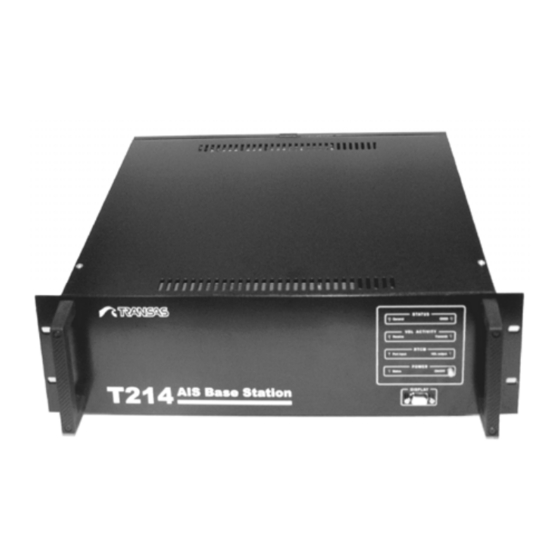
Printing house conventions Remote control and monitoring 2.2.2 Basic functionality AIS Base Station T214 can be controlled\monitored remotely through MAIN and AUX presentation ports. The basic remote control functions are listed below: • Base Station reset; • Channel Management; •... - Page 19 Hardware components Figure 2. GPS or GLONASS/GPS Antennae Figure 3. AIS Base Station main unit Figure 4. Cavity filter (OPTIONAL) Figure 5. Surge Protector IS-50UX-C0 (OPTIONAL) Chapter 2...
-
Page 20: Functional Diagram
AIS1 DISPLAY MAIN receiver RTCM Display AIS2 BIIT SENSOR receiver 1 PPS Power supply unit 24 Vdc Ethernet Digital I/O 24 VDC Indication board Figure 6. Functional diagram of AIS Base Station Т214 TRANSAS AIS BASE STATION T214. Technical Manual. -
Page 21: Technical Specifications
CHAPTER 3 Technical specifications This chapter provides technical specifications for AIS Base Station components. Copyright Transas Ltd., 2007... -
Page 23: Ais Base Station T214 Main Unit
AIS Base Station T214 main unit AIS BASE STATION T214 MAIN UNIT AIS Base Station T214 technical specification is provided in the table below: GNSS specification GPS receiver 12 channels, differential GNSS antenna Patch antenna with built-in 30dB preamplifier GLONASS receiver... -
Page 24: Vhf Antenna
Mast diameter, mm 38÷65 Rated wind velocity (no ice), m/s Load of side wind 45 m/s, N Wind loading area, m 0.07 Rated wind velocity with 0.5” icing, m/s Temperature range, °C -50 ÷ +50 TRANSAS AIS BASE STATION T214. Technical Manual. -
Page 25: Cavity Filter
Cavity filter Connector N-female Coating polymeric Electrical Specifications Operating frequency band, MHz 136÷174 VSWR, not more than Gain, OMNI dBd OFFSET Half power angle 70° Impedance, Ohm Max. Power input, W Adjustable fixed Polarization vertical H-plane pattern OMNI (1/2λ from mast), G0 = 0 dBd VSWR Diagram H-plane Pattern CAVITY FILTER... -
Page 26: Surge Protector
Connector terminations: N or UHF female Finish Acrylic enamel Net weight, lb (kg) 11 (5) Shipping weight, lb (kg) 14 (6.5) SURGE PROTECTOR Type: Polyphaser Surge protector IS-50NX-C2. Figure 7. Polyphaser Surge protector IS-50UX-C0 TRANSAS AIS BASE STATION T214. Technical Manual. - Page 27 Surge protector Figure 8. Surge protector dimensions Specifications: Characteristic Value Unit impedance: 50 Ohms Insertion Loss ≤ 0.1dB Frequency range: 1.5 ÷ 400 MHz Throughput voltage: ≤ 1100 Vpk Turn-on voltage: ±600 V Throughput energy: ≤ 10000.0000 µJ Insertion loss: 0.1dB VSWR: 1.2:1...
-
Page 29: Installation
CHAPTER 4 Installation This chapter provides information on the AIS Base Station installation procedures. Copyright Transas Ltd., 2007... -
Page 31: Installation Order
INMARSAT, GLOBAL STAR and IRIDIUM satellite terminals. This distance should in any case be not less than 4 m. It should not be within the radar radiation pattern. Antenna is connected to T214 unit with RG58/U cable using TNC-male connectors. The length of cable shall be less than 50m. -
Page 32: Gps Antenna Installation
GNSS antenna Installation GPS antenna installation 4.3.2 Two types of mounting kits are used to install GPS antenna: Figure 9. Mounting kit N220F Figure 10. Mounting kit N288F Figure 11. Dimensions of N288F TRANSAS AIS BASE STATION T214. Technical Manual. -
Page 33: Glonass/Gps Antenna Installation
To mount GLONASS/GPS antenna on vertical or horizontal pole the Mounting kit is used. Antenna is connected to T214 unit with 50 ± 5 Ώ RG213/U cable using connector UHF-male type on antenna end and TNC-male connector on the block end. The length of cable shall be less 30 m. -
Page 34: Vhf Antenna Installation
RG58/U 70dB @ 1.5 GHz 30 meters (50m – optional) GLONASS/GPS RG213/U 40 dB @ 1.5 GHz 30 meters (50m – optional with additional amplifier) RG213/U 7dB @ 150 MHz 30 meters TRANSAS AIS BASE STATION T214. Technical Manual. -
Page 35: T214 Main Unit Installation
Installation procedure 4.6.2 AIS Base Station T214 can be installed in 19” equipment rack with a depth of not less than 600 mm. Fix two slide rails inside of rack cabinet and install the AIS Base Station on these rails. Fix the Base Station from the front side with four screws. -
Page 36: External Connectors
T214 main unit installation External connectors 4.6.3 AIS Base Station T214 has the following external connectors: Connector Description Interface Purpose Comments type MAIN RS232 DB9F Main presentation Default parameters port are: 38400,8,N,1,(57600 may be set) RS232 DB9F Auxiliary Default parameters... - Page 37 T214 main unit installation The table below details I/O connector’s pin assignment: Description of pins Connector Name type connector Number Designation Interface type MAIN, RS232C DB9-female Not used Display 1,4,6-9 Not used SENSOR RS422 3,4,6-9 Not used RTCM Rx/Rx- RS232/RS422...
-
Page 38: Connections Of External Equipment
Devices interfaces port Source input/output port External Devices Figure 16. Connections of AIS Base Station to the external equipment Length of cables 4.6.5 Length of signal cables shall be less than 3 m. TRANSAS AIS BASE STATION T214. Technical Manual. -
Page 39: Power Supply Connection
T214 main unit installation Power supply connection 4.6.6 Basic power supply is 100÷240 VAC , 45÷65 Hz ; back up – 24VDC. Cable to connect «110-220 VAC, 45-65 Hz» shall have wire with area not less than 3х0.75mm with connectors like IEC 60320 C13 «Continental Europe». -
Page 41: User Configuration
CHAPTER 5 User configuration This chapter provides information on the AIS Base Station initial user configuration procedures. Copyright Transas Ltd., 2007... -
Page 43: Setting Up Of Serial Ports Parameters
Setting up of serial ports parameters SETTING UP OF SERIAL PORTS PARAMETERS The following external serial ports are available: • “Main” and “AUX” – presentation ports; • “Sensor” – input port for NMEA positioning or UTC time data; • “RTCM” – input port for RTCM differential connections data; •... -
Page 44: Display Port
Ethernet TCP\IP interface 5.2.1 The T214 AIS Base Station has Ethernet 10BASE-T interface which uses the TCP\IP protocol for the exchange of information with external users. The TCP\IP interface can be used for organising connection with the Base Station’s Main and AUX presentation ports. - Page 45 Before running the configuring utility disable Windows XP Firewall or any other Firewall software installed in the computer. The program will search for the T214 AIS Base Station devices included in the local network and will display the list of found devices sorted by MAC addresses.
- Page 46 After the input of the aforementioned parameters, the program will prompt you to confirm the data correctness. If everything is correct, enter “y”. New parameters will be applied and the program will produce a summary of current settings. TRANSAS AIS BASE STATION T214. Technical Manual.
-
Page 47: Internal Configuration
Setting TCP\IP parameters CHAPTER 6 Internal configuration This chapter provides information on the AIS Base Station internal configuration procedures. Chapter 6. Commissioning.Internal configuration... -
Page 49: Important Notes
AIS operating principles set forth in this Manual. Wrong settings can garble (destroy) VDL. During the setup of the AIS Base Station T214 internal parameters it is advisable to disconnect the VHF antenna. The settings entered for the Base Station are applied immediately after the exit from the Setup menu. -
Page 50: Operation With Service Display Program
“arrow-up” or “arrow-down” buttons (the chosen line is highlighted) and press the selection button in the right bottom corner of the screen. Exit from the submenu is by pressing the “Return” button. TRANSAS AIS BASE STATION T214. Technical Manual. - Page 51 Service Display program Where there is input of characters in the text box, a virtual keyboard is used. Keyboard keys are arranged on several screens. The purpose of control buttons is specified below: Prset to switch to the previous set of characters <- to move the cursor to the previous character ->...
- Page 52 Service Display program TRANSAS AIS BASE STATION T214. Technical Manual.
-
Page 53: Protection From Unauthorised Access
PROTECTION FROM UNAUTHORISED ACCESS Access levels 6.3.1 The AIS Base Station T214 settings can be protected with a password to prevent an accidental or unauthorised change in the operation mode. The Base Station implements four levels of access to various setup menus: •... -
Page 54: Setting New Administrator/Service Engineer Password
Setting new Administrator/Service engineer password 6.3.2 The Administrator password or the Service engineer password can be set in the Configuration->Setup->Admin password Configuration->Setup- >Engineer password menu respectively. If an empty password is set, protection is disabled. TRANSAS AIS BASE STATION T214. Technical Manual. -
Page 55: Recovering Forgotten Password
Protection from unauthorised access AIS Base Station Т214 is supplied with the disabled Administrator and Service engineer level protection. It is the user’s responsibility to enable the protection and safeguard the passwords. If the user finds the multi-level protection too bulky, some of the levels may be combined: •... -
Page 56: Setup Of Control Port Functions
Aux – auxiliary presentation port; • RTCM – reception of differential corrections. Corresponding to the aforementioned port assignment are the initial settings of their functions. These settings can be altered in the Configuration->Setup->Control setup menu. TRANSAS AIS BASE STATION T214. Technical Manual. - Page 57 Setup of control port functions For each of the ports (Main, Aux and RTCM) you can set functions to be performed by them. Description of options set for each control port: Parameter Description Defaults receive and process the Config data NMEA Main –...
- Page 58 RSSI (msg) – Received signal strength of each VDL message; Slot number – First slot number of each received message; Rx jitter – Time of message arrival (note1) S/nN ratio – Signal to noise ratio (note1); TRANSAS AIS BASE STATION T214. Technical Manual.
-
Page 59: Setup Of Serial Ports Parameters
Setup of serial ports parameters Chan. Load (last) – Previous frame channel load (note2); Bad CRCR cntr – Number of (messages with bad CRC) (note2); Chan. Load (forecast) – Forecast channel load (note2); Noise level – Average noise level (note2); RSSI (frame) –... -
Page 60: Adjusting List Of Output Alarm Messages
ADJUSTING LIST OF OUTPUT ALARM MESSAGES You can use the Configuration->Setup->Alarms menu for adjusting (On/Off) the list of alarms which will be output by AIS Base Station Т214. TRANSAS AIS BASE STATION T214. Technical Manual. -
Page 61: Navigational Data Sources Setup
Navigational data sources setup NAVIGATIONAL DATA SOURCES SETUP Navigational data sources 6.7.1 If there are several sources of navigational data (time, coordinates, differential data) AIS Base Station Т214 will be choosing the highest priority source. For the priority description, the concept of a “virtual navigational data sensor” is introduced. There are the following types of virtual sources: •... -
Page 62: Creating Virtual Sources Of Coordinates
Base Station with positioning data. If virtual sources of all the types are set to the initial condition (by using the “Reset” button), operation of AIS Base Station T214 in the part of receiving position data, is TRANSAS AIS BASE STATION T214. Technical Manual. -
Page 63: Assignment Of Synchronization Sources
Before connecting external sync source be sure that it has required parameters: NMEA sentence is tied to 1PPS with necessary tolerance. AIS Base Station T214 has the possibility to use second synchronization source connected to the following external ports: •... -
Page 64: Setup Of Differential Corrections Data Sources
If virtual sources of all the types are set to the initial condition (by using the “Reset” button), operation of AIS Base Station T214 in the part of receiving navigational data is in compliance with IEC-61993-2. The change of standard rules may be required for adapting the Base Station for the specific features of the particular coastal equipment. -
Page 65: Settings Of Base Station Configuration
RTCM data flow with text NMEA sentences may result in their incorrect identification. If the configuration sets a schedule for the transmission of differential corrections, AIS Base Station T214 will be sending on air sentence 17 containing differential corrections received via the serial port. SETTINGS OF BASE STATION CONFIGURATION The AIS Base Station requires a large number of various settings described in IEC- 62320-1. -
Page 66: Bcf - General Base Station Configuration
TxPower A, TxPower B – Power level channel A (high power=Nominal 12.5 Watts, low power=Nominal 2 Watts); Talker ID – Base Station talker ID; VDL retries – VDL message retries (1-10); Msg rep. indicator – Message repeat indicator (0-4). TRANSAS AIS BASE STATION T214. Technical Manual. -
Page 67: Cab - Control Ais Base Station
Settings of Base Station configuration CAB – Control AIS Base Station 6.8.2 This menu is used to turn on or off the transmission of channel A and B on an AIS Base Station. Base Station transmission schedule setup 6.8.3 TDMA algorithms The AIS stations exchange data on two TDMA VHF channels. - Page 68 “RAIM” flag shall be set to 0. 3. When the UTC sync source is unavailable, the AIS Base Station shall use UTC indirect (ITU-R M.1371-1 A2, 3.1.2) or the semaphore rules (ITU-R M.1371-1 A2, 3.1.1.4). TRANSAS AIS BASE STATION T214. Technical Manual.
- Page 69 ITU-R M.1371 messages 4, 17, 20 and 22 to the requestor. For the description of messages see under (Table 3. AIS Base Station T214 Input/Output Sentences Formatters). New CBM assignments will override CBM or ECB assignments.
- Page 70 CBM sentence is received from the AIS equipment. A null field indicates no change to the current start slot setting when sent to the AIS equipment, and indicates that the start slot has not been set, i.e. is unavailable, when the CBM TRANSAS AIS BASE STATION T214. Technical Manual.
- Page 71 Settings of Base Station configuration sentence is received from the AIS equipment. (ref. version of ITU-R M.1371-1 available on ITU WEB site). 2. Starting slot ranging from -1 to 2249 for ITU-R M.1371 messages 17, 20 or 22, broadcasts on Channels “A” or “B”. A value of –1 discontinues broadcasts of the message when the CBM sentence is sent to the AIS equipment, and indicates that no message has been broadcast if the CBM sentence is received from the AIS equipment.
- Page 72 1 for details. 3. For messages 17, 20, 22, or 23, starting slot ranging from 0 to 2249 should be used. A null field indicates no change to the current start slot setting when sent TRANSAS AIS BASE STATION T214. Technical Manual.
- Page 73 Settings of Base Station configuration to the Base Station, and indicates that the start slot has not been set, i.e. is unavailable, when the ECB sentence is received from the Base Station. 4. For messages other than message 17, this field is 1. For message 17 the number may range from 1 to 4 consecutive slots.
- Page 74 Timeout – Time out for reservation. The Time out in minutes ranging from 0 to 7 for the Slots reserved for FATDMA broadcasts. A null field indicates no change to the number of consecutive slots reserved when sent to the AIS equipment, and TRANSAS AIS BASE STATION T214. Technical Manual.
-
Page 75: System Setup Menu
System setup menu indicates that the number of consecutive slots has not been set, i.e. is unavailable, when the DLM sentence is received from the AIS equipment. SYSTEM SETUP MENU SystemId – The “Unique Identifier” is used for “system level identification of a device,”... -
Page 76: Input Of Regional Settings
Parameters of a new area are entered via the Configuration->AIS regions->NewRgn menu. Upon entry in the menu, after a prompt for and input of the administrator or service engineer password, a “New region” window opens up: TRANSAS AIS BASE STATION T214. Technical Manual. - Page 77 Input of regional settings The regional area parameters are set in separate windows via the virtual keyboard. Parameter values: South edge – area’s south border; North edge – area’s north border; East edge – area’s east border; West edge – area’s west border. Notation of coordinates: Degrees “...
-
Page 78: Ais Base Station Т214 Test Functions
(see ”Navigational data sources setup”) which currently provide a stable data flow. The source selected for use is marked with the ”!” sign. TRANSAS AIS BASE STATION T214. Technical Manual. -
Page 79: Monitoring Of Synchronization Data Source
AIS Base Station Т214 test functions Where standard sensor settings are used, the source numbers mean: Source Position number Coordinates from an external source connected to Sensor port and operating in the differential mode Coordinates from the internal GNSS operating in the differential mode Coordinates from an external source connected to Sensor port and operating in the normal mode Coordinates from the internal GNSS operating in the normal mode... -
Page 80: Technical Information
В / proceeding delay (number of slots passed from the beginning of packet to the moment of packet transmission to general proceeding algorithm ) / degree of sync instability of channel B; TRANSAS AIS BASE STATION T214. Technical Manual. -
Page 81: Alarms And Status Information
AIS Base Station Т214 test functions RcCnt batch counter on channel C ; TrCnt/DW/RW: transmitted packet counter / direct power / reflected power; Memory: memory (used/free) ; Fragmentation: free memory fragmentation number : range of minimal fragmentation – range of the biggest fragmentation. Characterizes the work of memory manager (heap) ;... - Page 82 Viewing of internal LOG file The T214 AIS Base Station has an internal LOG file which saves all the events significant from the viewpoint of diagnostics (alarms, change of status, BS turning off, firmware upgrade). To view internal LOG file press the Log file button.
-
Page 83: Using The Ais Base Station
CHAPTER 7 Using the AIS Base Station This chapter provides information on using the AIS Base Station T214. Copyright Transas Ltd., 2007... -
Page 85: Power Supply Connection
Function for automatic switchover to standby supply 7.1.3 The AIS Base Station T214 has a built-in function for the automatic switchover to the standby power supply. The Base Station controller diagnoses continuously the main and standby supply voltage. As the main supply voltage decreases to the value... -
Page 86: Connecting External Sensors And Pps Source
OPERATING FROM FRONT PANEL Switching ON\OFF 7.3.1 To switch ON the AIS Base Station T214 use the following procedure: • Connect the main power cable and turn on the power switch on the base Station rear panel: the Power Status LED on the front panel should light up in orange. -
Page 87: Indication Panel
Operating from front panel Indication panel 7.3.2 Led indicators for general diagnostic are located on front panel. They indicate the status of BS main components in accordance with Table 2: Table 2.. Front panel indication Indicator Name Functional status Description of indication group STATUS General... -
Page 88: Operating Using Remote Control Software
Operating using Remote Control software OPERATING USING REMOTE CONTROL SOFTWARE For the remote AIS Base Station T214 control, configuring and diagnostic, use the Remote Control software package included in the delivery set. The distribution disk includes two software components for the remote Base Station control: •... - Page 89 To set the access passwords for the specified functions, use the [Auth] section of the “bsc.ini” file. Password default values are defined as: [Auth] GUEST= USER=TRANSAS ADMINISTRATOR=NOBODY Running Base Station Controller program Run the Base Station Controller components by selecting the Start\Programs\Base Station Controller 2.20\Base Station Controller menu item.
- Page 90 Running Base Station Configurator program Run the Base Station Configurator by selecting the Start\Programs\Base Station Configurator 2.20\Base Station Configurator menu item. The screen will display the main Configurator console window. TRANSAS AIS BASE STATION T214. Technical Manual.
-
Page 91: Work With Remote Control Program
Operating using Remote Control software Work with Remote Control program 7.4.3 All the T214AIS Base Station operations described below are performed from the Base Station Configurator program console. Access levels 7.4.4 To ensure the safe access to the control and important Base Station configuration parameters, the Remote Control software has an authorisation system, and implements several access levels: •... - Page 92 BS. The “BS Statistics” group fields show the received message statistics. Extended diagnostics (IEC 62320-1) To obtain additional diagnostic data specified in the IEC 62320-1 standard, select the Extended (IEC62320-1) sub-tab: TRANSAS AIS BASE STATION T214. Technical Manual.
-
Page 93: Control And Extended Diagnostics
Operating using Remote Control software Control and extended diagnostics 7.4.7 To control the T214 Base Station and obtain its extended diagnostics, switch to the “BS Control” tab: The tab contains: • Power On/Off Control stay-put button for the remote power switching on/off. - Page 94 For more details on the purpose of fields and principles of configuring the Base Station schedule, see under 6.8.3. If the FATDMA schedule for the Base Station to be configured matches the IALA A- 124 format of the CBM type sentence, use the “Reporting” tab: TRANSAS AIS BASE STATION T214. Technical Manual.
- Page 95 Operating using Remote Control software If it is necessary to use FATDMA epochs and, accordingly, the parameters defined by the ECB sentence, use the “Extended” tab. Data Link Management slot allocations (DLM) To configure the slots reserved by the Base Station, use the “Data Link” sub-tab. For more details of the purpose of fields, see under 6.8.3.
- Page 96 Operating using Remote Control software Regional settings To configure regional channels select the “Regional Channels” tab. For more details of the purpose of fields, see under 6.10. TRANSAS AIS BASE STATION T214. Technical Manual.
-
Page 97: Necessary Conditions
Necessary conditions 8.1.1 The AIS Base Station T214 firmware upgrade can be made locally or remotely by using the Remote Control component detailed in the previous paragraph. For the upgrade operation to be performed, the Base Station Controller SW should be connected to the Base Station via both presentation ports (Main and Aux) as described under 7.4.2. - Page 98 Operating using Remote Control software Selecting firmware file Press the “Choose” button and specify the path to the T214 firmware file (a file with “.bin” extension). Switching on programming mode Press the “Switch” button: the Base Station will switch to the firmware upgrade mode.
- Page 99 Operating using Remote Control software After the successful firmware upgrade, the program will provide the following message: Switch off the programming mode by releasing the “Switch” button ! TTENTION Do not forget to switch off the programming mode by releasing the Switch button. Otherwise the Base Station Controller operation will be locked.
-
Page 101: Communication Protocol
CHAPTER 8 Communication protocol This chapter provides information on communication protocols applicable to AIS Base Station T214. Copyright Transas Ltd., 2007... -
Page 103: Main And Aux Presentation Ports
AIS Service”. Realization features are dealt with in the following subsections. AIS Base Station T214 receives/transmits messages 1-22 according to ITU-R M.1371-1 and messages 23, 24 – according to IEC 62287-1. Depend on Access Scheme (see 6.8.3) “... - Page 104 Rates for Base Station Messages with Epoch planning support Frame Summary of AIS Reception Installation Stations Identification Select Device’s Reception Processing and Output Transmit feed-back report – Base Station report status requested transmission TRANSAS AIS BASE STATION T214. Technical Manual.
-
Page 105: Proprietary Sentences
PI indicating the base station status. This shall be output once per minute or when there is a change in the status. PROPRIETARY SENTENCES AIS Base Station T214 accepts the following proprietary messages available on MAIN and AUX presentation ports: Power On\Off control commands. -
Page 106: Advanced Power Supply Status Sentences
Power OFF, 1 means Power ON). Advanced power supply status sentences 9.3.2 The advanced power supply status sentences are available only on the hardware versions of T214 with backup 24VDC power input. The following requests are available: Current power source request Request: !EIAIQ, UNIT=0, PWSRC=?*CS<CR><LF>... -
Page 107: Dgps Corrections Input Port
DGPS corrections input port Digital Outputs status request: Request: !EIAIQ,UNIT={1|2|3},DGOUT=?*CS<CR><LF> Answer: !AIPWR,UNIT={1|2|3},DGOUT={0|1}*CS<CR><LF> Digital Inputs status request: Request: !EIAIQ,UNIT={1|2|3},DGINP=?*CS<CR><LF> Answer: !AIPWR,UNIT={1|2|3}, DGINP={0|1}*CS<CR><LF> DGPS CORRECTIONS INPUT PORT The AIS Base Station has an interface to receive differential corrections. It is assumed that the AIS Base Station receives differential corrections (in RTCM format) via this interface with subsequent passing them to the AIS channels. -
Page 109: List Of Alarms And Troubleshooting
CHAPTER 9 List of alarms and troubleshooting This section contains a list of alarms, statuses, faults and methods to remove them. Copyright Transas Ltd., 2007... -
Page 111: List Of Alarms
List of alarms LIST OF ALARMS 10.1 All the malfunctions are divided into five groups: 1) Complete failure of the main unit including auto testing system failure; 2) Complete failure of the main unit, diagnostics provided on the Service Port; 3) Partial failure of the main unit with the diagnostics AISALR messages provided on the presentation interface and on the Service Port;... - Page 112 UTS clock lost Independent – follow synchronisation rules including semaphore. Dependent – follow synchronisation rules. Stop transmission when there is no synchronisation source. External DGNSS in use Continues operation External GNSS in use Continues operation TRANSAS AIS BASE STATION T214. Technical Manual.
-
Page 113: Troubleshooting
Troubleshooting Text description of state Identifier System state (response) (number) Internal DGNSS Continues operation (beacon) Internal DGNSS Continues operation (message 17) Internal GNSS in use Continues operation Channel control parameters Continues operation with region re- have been changed or there assignment has been region re-assignment UTC clock found... - Page 114 Station Т 214. If the setup is Restore the cable if the correct, appropriate tools and connection materials are available. cable may be broken. Serial port Contact service burned off. centre. TRANSAS AIS BASE STATION T214. Technical Manual.
- Page 115 (see under “Creating Virtual connected. Sources Coastal AIS Base Station T214 Equipment Coordinates”). Incorrect Set up interfaces in the interface setup menu. setup. If the setup is Restore the cable if the...
Need help?
Do you have a question about the T214 and is the answer not in the manual?
Questions and answers