Table of Contents
Advertisement
Quick Links
Advertisement
Table of Contents

Related Manuals for Jackson Labs Mini-JLT GNSS

Summary of Contents for Jackson Labs Mini-JLT GNSS
-
Page 1: User Manual
Mini-JLT GNSS™ User Manual Document: 80200549 Version: Date: 28 August, 2017... - Page 2 Mini-JLT GNSS™ User Manual Copyright © 2017 Jackson Labs Technologies, Inc.
-
Page 3: Table Of Contents
3.3.22GPS:SURVey:DURation <sec> ....22 3.3.23GPS:SURVey:VARIANCE <mm2> ....22 © 2017 Jackson Labs Technologies, Inc. - Page 4 3.9.1 SYSTem:COMMunicate ..... . 31 3.9.1.1 SYSTem:COMMunicate:SERial:ECHO ... . . 31 © 2017 Jackson Labs Technologies, Inc.
- Page 5 6.1.2 Limitation of Warranty ......55 6.1.3 Exclusive Remedies ......56 © 2017 Jackson Labs Technologies, Inc.
- Page 6 Mini-JLT GNSS™ User Manual © 2017 Jackson Labs Technologies, Inc.
-
Page 7: Introduction
NMEA and SCPI communication commands, and removes support for TSIP proprietary commands. The Mini-JLT GNSS™ GPSDO uses a multi-GNSS receiver that can run in stationary (Position Hold mode) and mobile mode to discipline an OCXO local oscillator to better than 1ppb frequency accuracy. -
Page 8: General Safety Precautions
GNSS antenna feed to prevent damage, injury, and/or death in case of a lightning strike. 1.2.2 Grounding To avoid damaging the sensitive electronic components in the Mini-JLT GNSS™ GSPDO always make sure to discharge any built-up electrostatic charge to a good ground source, such as power supply ground. -
Page 9: Quick-Start Instructions
1) Connect a 3.3V or 5V-compatible GNSS antenna to SMA connector J4. The antenna can be passive or active. The Mini-JLT GNSS™ board will supply 3.3V to the antenna by default, and this can be increased to up to 5.5V through the external antenna power supply... -
Page 10: Pcb Photos
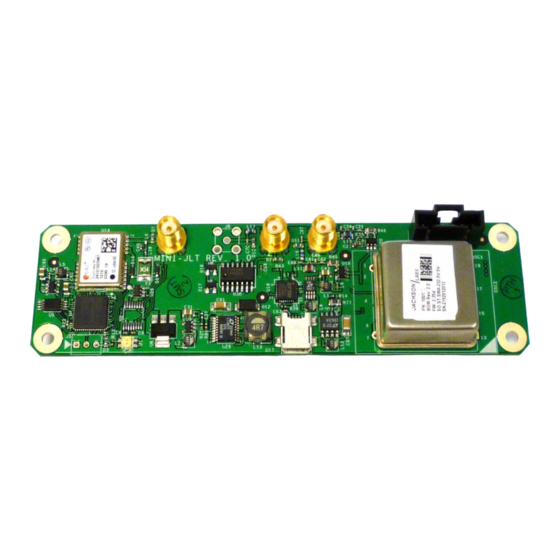
2.1.1 PCB Photos PCB is shown in Figure 2.1. Mini-JLT GNSS™ Figure 2.1 Mini-JLT GNSS™ Single Oven PCB 2.1.2 Mechanical Drawings The following drawings show the mechanical dimensions and the pinout of the Mini-JLT GNSS™ PCB: © 2017 Jackson Labs Technologies, Inc. - Page 11 Mini-JLT GNSS™ User Manual Figure 2.2 Mini-JLT GNSS™ Mechanical Dimensions Table 2.1shows the Mini-JLT GNSS™ revision 1.0 hardware pin descriptions Table 2.1 Mini-JLT GNSS™ hardware connectors Name Function Specification Description J1 Pin 1 1PPS In Optional external 1PPS 0V to 5V, pulled-low by 4.7K...
-
Page 12: Notes On Signal Interfacing
The serial port RX and TX lines cannot be directly connected to a DB9 connector as these are driven with TTL signal levels. Connecting these pins to an RS-232 serial interface may damage the board. © 2017 Jackson Labs Technologies, Inc. -
Page 13: Coaxial Connectors
USB power will not be used to drive circuits on the PCB. 2.3 Multi-GNSS Capabilities The Mini-JLT GNSS™ is capable of simultaneously receiving multiple GNSS systems at one time. Concurrent GNSS operation aids performance by allowing reception of up to 72 GNSS satellites in challenged reception areas such as in urban canyons, under foliage, indoors, or close to the earth's poles, etc. -
Page 14: Connecting The Gnss Antenna
GNSS receiver is a 72 channel high-sensitivity multi-GNSS receiver with very fast lock time. The Mini-JLT GNSS™ unit is set at the factory to use Position Hold mode, and will initiate an Auto Survey process after power-on to establish its new position. The Auto Survey process may last up to 3 hours. - Page 15 Phase compensation: this is the Integral part of the PID loop. This corrects phase offsets between the Mini-JLT GNSS™ 1PPS signal and the UTC 1PPS signal as generated by the GNSS receiver. Set higher values for tighter phase-following at the expense of frequency stability. Typical values range from 4 - 30, 25 being the default.
- Page 16 Mini-JLT™ User Manual Figure 2.3 Mini-JLT GNSS™ phase compensation plot © 2017 Jackson Labs Technologies, Inc.
-
Page 17: Scpi-Control Quick Start Instructions
There are a number of commands that can be used as listed below. Most of these are identical or similar to Symmetricom 58503A commands. To get a listing of the available commands, send the HELP? query. This will return a list of all the available commands for the Mini-JLT GNSS™ GPSDO. -
Page 18: Help
This query returns a list of the commands available for the Mini-JLT GNSS™ GPSDO. 3.3 GPS Subsystem Note: Please note that Mini-JLT GNSS™ displays antenna height in MSL Meters rather than in GPS Meters on all commands that return antenna height [the legacy Fury GPSDO uses GPS height]. The NMEA position fixes are in the WGS84 coordinate system, while the X,Y, and Z velocity vectors are given in the ECEF coordinate system. -
Page 19: Gps:satellite
Mini-JLT GNSS™ serial interfaces. Once enabled, Mini-JLT GNSS™ will send out information on the TTL and USB serial transmit pin automatically every N seconds. All incoming serial commands are still recognized by Mini-JLT GNSS™... -
Page 20: Gps:gpgga
Mini-JLT GNSS™ User Manual 3.3.5 GPS:GPGGA This command instructs the Mini-JLT GNSS™ to send the NMEA standard string $GPGGA every N seconds, with N in the interval [0,255]. The command is disabled until the GNSS receiver achieves a first fix. -
Page 21: Gps:xyzspeed
This command has the following format: GPS:GPZDA <int> [0,255] 3.3.11 GPS:PASHR The NMEA string $PASHR,POS has been added for compatibility to legacy GPS hardware. The PASHR command alongside the GPZDA command will give all relevant parameters such as time, © 2017 Jackson Labs Technologies, Inc. -
Page 22: 12Gps:gyro
00.0Static number p.pp:Firmware Version (1.05 and above) This command instructs the Mini-JLT GNSS™ to send the NMEA standard string $PASHR every N seconds, with N in the interval [0,255]. The command is disabled until the GNSS receiver achieves a first fix. -
Page 23: 13Gps:gyro:cal
GPS:GYRO:CAL -3, 0, 0, 1, 1, 1 This will remove a 3 Degree offset from the X Axis, and keep the Y and Z axis without offset or gain adjustments. © 2017 Jackson Labs Technologies, Inc. -
Page 24: 14Gps:dynamic:mode
The GNSS receiver will perform Carrier Phase tracking for non-airborne modes. The command has the following syntax: GPS:DYNAMic:MODE <int> [0,8] Sending the following command to the Mini-JLT GNSS™ will select a stationary GNSS dynamic model for example: gps:dynam:mode 1 The following table lists all available modes:... -
Page 25: 15Gps:dynamic:mode 8 (Automatic Dynamic Mode)
Select one of the above states (0 – 7) based on the actual velocity of the vehicle The Mini-JLT GNSS™ GPSDO uses a GNSS receiver that is capable of running in a stationary mode with Position Auto Survey called Position Hold Mode. This mode increases timing stability by storing the position into memory, and solving the GNSS signal only for time as the position is not expected to change. -
Page 26: 16Gps:dynamic:state
GPS:TMODE, as the Position Hold mode setting overrides any dynamic state user setting. Settings will be applied immediately to the GNSS receiver, and are stored in Non Volatile memory. © 2017 Jackson Labs Technologies, Inc. -
Page 27: 17Gps:reference:adelay
It takes approximately 1 minute for locking to commence after a GNSS receiver reset, as indicated by the red blinking LED. 3.3.20 GPS:TMODe <ON|OFF|RSTSURV> This command selects the Timing Mode of the GNSS receiver. © 2017 Jackson Labs Technologies, Inc.[-32767Ns,32767Ns] -
Page 28: 21Gps:survey Once
This query specifies the duration of the survey in progress or the last survey. 3.3.26 GPS:SURVEY:STATUS? This query displays the current status of the survey. The status of the survey is in one of the 3 states: ACTIVE : a survey is in progress © 2017 Jackson Labs Technologies, Inc. -
Page 29: 27Gps:initial:date
GPS:SYST:SEL GPS SBAS GAL GLO The following command will query the currently enabled GNSS systems: GPS:SYST:SEL? The Mini-JLT GNSS™ will respond to the query with the list of enabled GNSS systems like: GPS SBAS GAL GLO © 2017 Jackson Labs Technologies, Inc. -
Page 30: 30Gps:jamlevel
3.3.32 GPS? This query displays the configuration, position, speed, height and other relevant data of the GNSS receiver in one convenient location. 3.4 GYRO SUBSYSTEM The following Gyro commands are supported on the Mini-JLT GNSS™ unit: GYRO:MODE <ON | OFF> GYRO:TRACE <int>... -
Page 31: Gyro:cal:compute
This query returns the current calendar date. The local calendar date is referenced to UTC time. The year, month, and day are returned. 3.5.2 PTIMe:TIME? This query returns the current 24-hour time. The local time is referenced to UTC time. The hour, minute, and second is returned. © 2017 Jackson Labs Technologies, Inc. -
Page 32: Ptime:time:string
59, 60 or 61 if GPS Almanac data is available, and 0 otherwise. A response of 60 indicates that no leap second is pending. 3.5.10 PTIME? This query returns at once the result of the four following queries: PTIME:DATE? PTIME:TIME? PTIME:TZONE? © 2017 Jackson Labs Technologies, Inc. -
Page 33: Synchronization Subsystem
1PPS output and the GNSS receiver 1PPS by using the SYNC:TINT? command. This allows the user to see the OCXO drift when not locked to GNSS signals for testing purposes, or to prevent the GNSS receiver from being spoofed and affecting the OCXO frequency © 2017 Jackson Labs Technologies, Inc. -
Page 34: Synchronization:holdover:recovery:initiate
This query returns the Frequency Error Estimate, similar to the Allan Variance using a 1000s measurement interval and comparing the internal 1PPS to GPS 1PPS offset. Values less than 1E-012 are below the noise floor, and are not significant. © 2017 Jackson Labs Technologies, Inc. -
Page 35: 10Synchronization:locked
UTC phase offset is > 250ns then the following errors would be indicated: 1) UTC phase > 250ns: 0x4 2) OCXO voltage too high: 0x40 3) GNSS receiver in holdover: 0x10 ‘Oring’ these values together results in: © 2017 Jackson Labs Technologies, Inc. -
Page 36: 13Synchronization
This command returns the number of hours the unit has been powered-on. 3.8 MEASURE Subsystem This subsystem regroups the queries related of some parameters that are measured on-board on the Mini-JLT™. The list of the commands supported for this subsystem is the following: © 2017 Jackson Labs Technologies, Inc. -
Page 37: Measure:voltage
3.9.1.2 SYSTem:COMMunicate:SERial:PROmpt This command enables/disables the prompt “scpi>” on the SCPI command lines. The prompt must be enabled when used with the software GPSCon. This command has the following format: SYSTem:COMMunicate: SERial:PROmpt <ON | OFF> © 2017 Jackson Labs Technologies, Inc. -
Page 38: System:communicate:serial:baud
The FASTlock command enables the FASTLOCK mode, and sets its gain parameter. Fastlock works by momentarily multiplying the EFCScale gain to a value determined by this SERVo:FASTlock parameter. Gain values of 1x to 20x can be set, with a gain of 1x effectively disabling the FASTLOCK feature. © 2017 Jackson Labs Technologies, Inc. -
Page 39: 2Servo:falength
This command sets the coarse DAC that controls the EFC. The Mini-JLT™ control loop automatically adjusts this setting. The user should not have to change this value. This command has the following format: SERVo:COARSeDac <int> [0,225] © 2017 Jackson Labs Technologies, Inc. -
Page 40: 4Servo:dacgain
This parameter is a coefficient that represents the drift of the EFC needed to compensate the natural drift in frequency of the OCXO due to aging. This coefficient is automatically computed and adjusted over time by the Jackson Labs Technologies, Inc. firmware. This command has the following format: SERVo:AGINGcompensation <float> [-10.0, 10.0] 3.10.10 SERVo:PHASECOrrection... -
Page 41: 11Servo:1Ppsoffset
Mini-JLT GNSS™ User Manual 3.10.11 SERVo:1PPSoffset This command sets the Mini-JLT GNSS™ 1PPS signal’s offset to UTC in 16.7ns steps. Using the SERV:1PPS command results in immediate phase change of the 1PPS output signal. This command has the following format: SERVo:1PPSoffset <int>... - Page 42 Mini-JLT GNSS™ User Manual SERVo:SLOPe? SERVo:TEMPCOmpensation? SERVo:AGINGcompensation? SERVo:PHASECOrrection? SERVo:1PPSoffset? SERVo:TRACe? © 2017 Jackson Labs Technologies, Inc.
-
Page 43: Firmware Upgrade Instructions
Firmware Upgrade Instructions 4.1 Introduction The following is a short tutorial on how to upgrade the Mini-JLT GNSS™ GPSDO firmware. Please follow the instructions in-order to prevent corrupting the Mini-JLT GNSS™ Flash, which may require reflashing at the factory. With some practice, the entire Flash upgrade can be done in less than one minute, even though the following seems like a fairly long list of instructions. -
Page 44: Flash Magic Flash Programming Utility
4.3 Putting the PCB into In-Circuit Programming (ISP) mode Momentarily short-out the ISP# pin 2 of header J5 to pin 1 of header J5 of the Mini-JLT GNSS™ board to ground the ISP# pin during power-on. It may be useful to connect a push-button to pin 1 and pin 2 of J5 to allow in-field firmware upgrades on the Mini-JLT GNSS™... - Page 45 Also, please point the “Filename” to the directory where you have stored the latest firmware hex file that is to be downloaded. D) Start the download by pressing “Upload to Flash” button. The following window should appear if the correct COM port has been chosen etc.: © 2017 Jackson Labs Technologies, Inc.
-
Page 46: Flash Magic Flash Programming Utility
RENDER THE PCB USELESS AND CAN ONLY BE RECOVERED AT THE FACTORY! 4.4.2 Flash Magic Flash Programming Utility A) Open the Flash Magic utility. Set the COM port in the Flash Magic application as needed on your PC. Set “Interface” to “None (ISP)”. © 2017 Jackson Labs Technologies, Inc. - Page 47 Mini-JLT GNSS™ User Manual Figure 4.3 Flash Magic utility B) Press the “Select Device” button and the window shown in Figure 4.4 will appear: © 2017 Jackson Labs Technologies, Inc.
- Page 48 Mini-JLT GNSS™ User Manual Figure 4.4 Device selection window C) Expand the ARM7 folder and select the appropriate processor, in this case the LPC2138. © 2017 Jackson Labs Technologies, Inc.
-
Page 49: Verifying Firmware Update
During power on, the unit sends an ID string out of the serial port at 115200 Baud by default. The firmware version can also be queried by sending the *IDN? command. Verify that the firmware version is the version that was downloaded. © 2017 Jackson Labs Technologies, Inc. - Page 50 Mini-JLT GNSS™ User Manual © 2017 Jackson Labs Technologies, Inc.
-
Page 51: Gpscon Utility
GPSCon Utility 5.1 Description GPSCon - Jackson Labs Edition is a program for the monitoring and control of a Jackson Labs Technologies, Inc. GPSDO, Simulator and receiver products. It communicates with the receiver using the SCPI command set. This free version of the GPSCon utility is compatible only with... -
Page 52: Communication Parameters
6. See “Trace position” diagram for the arrangement of the trace positions in the trace window. In this example the data obtained from the meas:current? query will be plotted in trace position 6. © 2017 Jackson Labs Technologies, Inc. -
Page 53: Traces Parameters
Any of the eight traces can be replaced by auxiliary traces as described in Section 5.3.1.2 . Press the “Help” button for a full description of each option in the Traces tab. Figure 5.2 Setting the communications parameters © 2017 Jackson Labs Technologies, Inc. - Page 54 Mini-JLT GNSS™ User Manual Figure 5.3 Auxiliary Parameters window Figure 5.4 Traces Parameters window © 2017 Jackson Labs Technologies, Inc.
-
Page 55: Sending Manual Commands To The Receiver
Mini-JLT GNSS™. Once you’ve selected the command you can press “Send” to send it to the Mini-JLT GNSS™. You can also send common commands by clicking on the buttons below the message window. You can hover over the buttons to see the exact command that is sent. - Page 56 When you have locked the start and stop time using the mouse, you can scroll left or right through the data. To scroll to a later time, use Shift + Left click. To scroll to an earlier time, use Shift + Right click. Figure 5.6 Graph display © 2017 Jackson Labs Technologies, Inc.
-
Page 57: Exporting The Graphics
The export may be done automatically on a timed basis. Simply enter a non-zero value in seconds to choose an export time interval. To manually export in accordance with the settings, press the 'Export' button. © 2017 Jackson Labs Technologies, Inc. -
Page 58: Interpreting The Data
5.4 Interpreting the Data Figure 5.8 shows the data acquired by the Mini-JLT GNSS™ unit over a period of more than 200 hours The red trace is EFC (crystal frequency control voltage). The crystal is aging (becoming faster in frequency over time). This requires the control voltage to be lowered to maintain precisely 10.0MHz. - Page 59 The unit disciplines its internal 10MHz reference to within less than +/-80ns peak to peak of UTC at all times, which is less than one complete clock cycle at 10MHz. © 2017 Jackson Labs Technologies, Inc.
- Page 60 Mini-JLT GNSS™ User Manual © 2017 Jackson Labs Technologies, Inc.
-
Page 61: Certification And Warranty
Except for products returned to Customer from another country, Jackson Labs Technologies, Inc. shall pay for return of products to Customer. If Jackson Labs Technologies, Inc. is unable, within a reasonable time, to repair or replace any product to condition as warranted, the Customer shall be entitled to a refund of the purchase price upon return of the product to Jackson Labs Technologies, Inc. -
Page 62: Exclusive Remedies
User Manual PURPOSE. No license, express or implied, by estoppel or otherwise, to any intellectual property rights is granted by this document. Jackson Labs Technologies, Inc. products are not intended for use in medical, life saving, or life sustaining applications.
Need help?
Do you have a question about the Mini-JLT GNSS and is the answer not in the manual?
Questions and answers