Sign In
Upload
Download
Table of Contents
Contents
Add to my manuals
Delete from my manuals
Share
URL of this page:
HTML Link:
Bookmark this page
Add
Manual will be automatically added to "My Manuals"
Print this page
×
Bookmark added
×
Added to my manuals
Manuals
Brands
Memmert Manuals
Accessories
INCO 108
Operating manual
Memmert INCO 108 Operating Manual
Co2 incubators
Hide thumbs
1
2
3
Table Of Contents
4
5
6
7
8
9
10
11
12
13
14
15
16
17
18
19
20
21
22
23
24
25
26
27
28
29
30
31
32
33
34
35
36
37
38
39
40
41
42
43
44
45
46
47
48
49
50
51
52
53
54
55
56
57
58
59
60
61
62
63
64
page
of
64
Go
/
64
Contents
Table of Contents
Bookmarks
Table of Contents
Manual, the Term INCO Is Used for INCO as Well as Incomed for the Purpose of Simplification
Table of Contents
1 Safety Regulations
Safety Regulations
Terms and Icons Used
Product Safety and Dangers
Behaviour in Case of Malfunctions and Irregularities
Changes and Conversions
Requirements of the Operating Personnel
Responsibility of the Owner
Switching off Incubator in an Emergency
What to Do in Case of Accidents
Design and Function
Function
Optional Extras
Material
Electrical Equipment
Connections
Intended Use
EC Declaration of Conformity
Designation (Nameplate)
Technical Data
Ambient Conditions
Accessories Included
Delivery, Transport and Setting up
Safety Regulations
Transport
Delivery
Setup
Putting into Operation
Connecting
Oxygen Calibration
Operation and Control
Opening the Door
Loading the Incubator
Inserting Water Tray(S)
Connect Gas Supply
Switch on Appliance
Basic Operation
Setting Parameters
Operating Modes
Setting the Operating Mode
During Operation
Ending Operation
Warning Messages and Malfunctions
Warning Messages
System/Appliance Errors
Power Failure
Advanced Functions
Printer
Basic Appliance Settings (Setup)
Temperature Monitoring
Sterilisation Chipcard
User ID Card (Optionally Available as an Accessory)
Calibration
Communication Interfaces
Log Memory
Maintenance and Servicing
Regular Maintenance
Adjusting Door
Repairs and Service
Storage and Disposal
Storage
Disposal
Index
Advertisement
Quick Links
1
Function
2
Technical Data
Download this manual
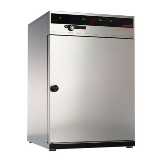
OPERATING MANUAL
CO
incubators
2
INCO 108
INCO 108 med
INCO 153
INCO 153 med
INCO 246
INCO 246 med
Table of
Contents
Previous
Page
Next
Page
1
2
3
4
5
Advertisement
Table of Contents
Need help?
Do you have a question about the INCO 108 and is the answer not in the manual?
Ask a question
Questions and answers
Related Manuals for Memmert INCO 108
Accessories Memmert UN 30 Operating Instructions Manual
Unxx series, ufxx series, inxx series, ifxx series universal oven (48 pages)
Accessories Memmert INCO 153 Operating Manual
Co2 incubators (64 pages)
Accessories Memmert INCO 246 Operating Manual
Co2 incubators (64 pages)
Accessories Memmert ICO Operating Manual
Co2 incubator ico (68 pages)
Accessories Memmert PERFECT Operating Instructions Manual
Cooled incubator with peltier technology and cooled incubator with refrigeration unit (48 pages)
Accessories Memmert IPP 200 Service Manual
Cooled incubator with peltier technology and constant climate chamber with humidification (48 pages)
Accessories Memmert IPP300 Service Manual
Cooled incubator with peltier technology and constant climate chamber with humidification (48 pages)
Accessories Memmert IPP400 Service Manual
Cooled incubator with peltier technology and constant climate chamber with humidification (48 pages)
Accessories Memmert IPP500 Service Manual
Cooled incubator with peltier technology and constant climate chamber with humidification (48 pages)
Accessories Memmert IPP Series Operating Instructions Manual
Peltier-cooled incubator, storage cooled incubator (44 pages)
Accessories Memmert IPS Series Operating Instructions Manual
Peltier-cooled incubator, storage cooled incubator (44 pages)
Accessories Memmert IPS 750 Operating Instructions Manual
Peltier-cooled incubator, storage cooled incubator (44 pages)
Accessories Memmert ICOmed Series Operating Manual
Co2 incubator icomed with ivf module (24 pages)
Accessories Memmert HPP Operating Instructions Manual
Constant climate chamber, cooled incubator (68 pages)
Accessories Memmert HPP Operating Instructions Manual
Constant climate chamber, cooled incubator (64 pages)
This manual is also suitable for:
Inco 108 med
Inco 153
Inco 246 med
Inco 153 med
Inco 246
Table of Contents
Save PDF
Print
Rename the bookmark
Delete bookmark?
Delete from my manuals?
Login
Sign In
OR
Sign in with Facebook
Sign in with Google
Upload manual
Upload from disk
Upload from URL


Need help?
Do you have a question about the INCO 108 and is the answer not in the manual?
Questions and answers