Table of Contents
Advertisement
Advertisement
Table of Contents

Related Manuals for TAGSYS RFID Medio L400


Summary of Contents for TAGSYS RFID Medio L400
- Page 1 Medio L400 User's Guide Revision 1.8 June 2008...
-
Page 2: Publishing Information
Medio L400 Publishing Information Disclaimer and Limitation of Liability All information herein is either public information or is the property of and owned solely by TAGSYS who shall have and keep the sole right to file patent applications or any other kind of intellectual property protection in connection with such information. -
Page 3: Read This First
Welcome to the TAGSYS range of products operating at the 13.56 MHz frequency. This range of products is used to implement high-quality RFID systems for demanding applications. This document provides information about how to install and use the Medio L400 reader. Audience This document requires familiarity with RFID technology. -
Page 4: Quality Issues
Medio L400 Quality Issues TAGSYS implements stringent quality controls at all stages of its manufacturing process. However, should you find a defect with this product, please notify your TAGSYS Quality Service representative using the dedicated Product Return Form. Telephone: +33 (0)4 91 27 57 36... -
Page 5: Table Of Contents
Read This First Table of Contents PUBLISHING INFORMATION __________________________________________________________ 2 ___________________________________________________ 2 ISCLAIMER AND IMITATION OF IABILITY READ THIS FIRST ____________________________________________________________________ 3 _____________________________________________________________________________ 3 UDIENCE _________________________________________________________________________ 3 ONVENTIONS ________________________________________________________________ 3 F YOU NEED ASSISTANCE _______________________________________________________________ 3 ONTACT FOR OMMENTS _______________________________________________________________________ 4 UALITY SSUES 1 FOR YOUR SAFETY _______________________________________________________________ 7... - Page 6 Medio L400 4.6 R _______________________________________________ 24 ESTORING ACTORY ONFIGURATION 4.7 R _____________________________________ 24 UNNING AGSYS XPLORER FOR THE IRST 4.7.1 I ___________________________________________________ 24 NSTALLING AGSYS XPLORER 4.7.2 C __________________________ 26 ONNECTING TO A DEVICE USING AGSYS XPLORER IZARD 4.7.3 R...
-
Page 7: For Your Safety
1 For Your Safety 1.1 General Use The Medio L400 reader is designed to be reliable and to provide continuous, trouble-free service. Please observe the following general tips: Take care not to scratch the device. Keep the device clean. When working with the device, use only TAGSYS-approved accessories. -
Page 8: Important Safety Information
Medio L400 1.3 Important Safety Information 1.3.1 Operating Environment When connecting the device or any accessory to another device, read its user’s guide for detailed safety instructions. Do not connect incompatible products. As with all RF equipment, users are advised that the equipment should only be used in its normal operating mode described in this document. -
Page 9: Certification
Article Surveillance (EAS), Radio Frequency Identification (RFID) and similar applications” in conjunction with the European Standard EN 50357 describing how to evaluate the exposure level. It is the responsibility of the TAGSYS Partner to install the Medio L400 as described in TAGSYS Documentation and with the appropriate antennas. -
Page 10: Fcc Id Cross Reference Table
2.2.2 FCC ID Cross Reference Table It is the responsibility of the TAGSYS Partner to install the Medio L400 as described in the table below, taking care of only installing the right antenna configuration with the right power settings. Table 1: Medio L400-2 FCC ID Cross reference Table Max. - Page 11 Certification Table 2: Medio L400-4 FCC ID Cross reference Table Max. Outside Channel Antenna Multiplexer Output Power Supply FCC ID Dimension Setting Power TR-CAU Quad- 170X900 FDF0453-A QHKMEDIOL400CHAN4 Antenna Channel Aero LB Quad- 250X250 FDF0453-A QHKMEDIOL400CHAN4 Antenna Channel Tunnel Quad-...
- Page 12 Medio L400 In ISO15693 Parameters window set the uplink parameters as follow: Command modulation depth: 10% (ASK) EOF modulation depth: 10% (ASK) Data coding mode: 1 of 256 12/51 Revision 1.8 June 2008...
-
Page 13: In Usa (Fcc Directive)
2.2.3 In USA (FCC Directive) The Medio L400 has been designed to comply with Part 15 of the FCC Rules. Furthermore typical configurations listed section 2.2.2 have been successfully tested with Part 15 of the FCC rules (FCC ID Numbers are listed on all system-mounted TAGSYS Antennas). -
Page 14: I Ncanada
(e.i.r.p) is no more than that permitted for successful communication. The Medio L400-2 device has been designed to operate with the antennas listed below, and having a maximum gain of -25 dBi. Antenna not included in this list or having a gain greater than - 25 dBi are striclly prohibited for use with this device. -
Page 15: Overview
Overview 3 Overview The Medio L400 is a long-range 13.56MHz RFID reader intended for RFID applications requiring a high performance, long range RFID infrastructure. The L400 uses advances in Digital Signal Processing (DSP) and RF Front End technology to achieve breakthrough performance in read range and read speed with industry leading signal to noise ratio. -
Page 16: Key Features
. RF power amplifiers consumption . RF power amplifiers operating temperature . Antennas tuning status, . Real-time Raw signal capture, … Firmware Remotely upgradeable 3.2 Delivery The Medio L400 reader kit contains the following items: 16/51 Revision 1.8 June 2008... -
Page 17: Physical Description
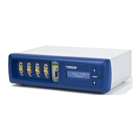
(Up, Down, Select) • RF connectors and status LEDs : The medio L400 can handle up to 2 (Medio L400-2) or 4 (Medio L400-4) antennas. The connectors provided are SMA (SMA/BNC adapters are supplied with the reader). RF output power is software selectable from 500mW to 5W (+/- 10%) in 250mW increments. - Page 18 Medio L400 Table 5: RF Status LEDs Description Green Description RF field is OFF. RF field is ON and channel antenna tuning and operating temperature are correct. BLINKING RF field is ON but channel is close to maximum operating temperature.
- Page 19 Overview previous information page, pressing the “Down” key jumps to next information page, Holding the “Select” key displays more information (if available). June 2008 Revision 1.8 19/51...
- Page 20 Medio L400 Table 8: LCD Screen Pages description Description (“Select” Page Description (“Select” key not pressed) key pressed) Product name Operating system version Radio firmware version Date and Time Current Ethernet IP address, or “Interface down” if ethernet interface is not...
-
Page 21: Rear Panel
Overview 3.3.2 Rear Panel The rear panel is dedicated to the power supply and communication connectors. Figure 2: Rear panel 10/ 100 Ethernet Connector RJ 45 connector (Please refer to the Ethernet network cabling rules). USB Connector USB connector type B. Use standard A/B cable to connect to the host. RS-232 Connector Male DB-9 connector. -
Page 22: Installation
4.1 Mechanical Aspects The Medio L400 is delivered with four rubber pads on the bottom of the package for installation on a table or desktop. The rubber pads can be removed to access the screw cutting hole that can be used to mount the unit in various positions. -
Page 23: Using Usb Interface
The virtual COM port (VCP) driver. The VCP driver emulates a standard PC COM port. After installation of the drivers, power up and connect your Medio L400 to a spare USB port on your PC to launch the Windows Found New hardware Wizard Select “No, not this time”... -
Page 24: Restoring Factory Configuration
4.7 Running Tagsys Explorer for the First Time The Medio L400 reader is delivered with the Tagsys Explorer software tool intended to easily setup the reader, test it and perform RFID reading and writing operations. In addition, the L400 Explorer can be used to display additional information about the reader (Firmware and hardware versions and revisions) as well as to upgrade reader firmware. - Page 25 Installation 2. In Windows Explorer, open the CD-ROM drive window and run “Tagsys Explorer Installer.msi” in “Tagsys Explorer” folder. Figure 3: Setup Welcome window 3. Click Next to view the license agreement, then click Next again if you agree with the terms. 4.
-
Page 26: Connecting To A Device Using Tagsys Explorer Wizard
Medio L400 5. Once the correct folder is selected, click Next. Figure 5: Confirm Installation window 6. Click Next to start the installation process. A shortcut will be created on your desktop and a program group will be created in the start menu. - Page 27 Installation Figure 6: Tagsys Explorer window Menu bar Toolbar Status bar The “Tagsys Explorer Wizard” opens automatically when Tagsys Explorer is started for the first time. This wizard allows you to quickly set up the Tagsys Explorer to perform basic tasks such as configuring your RFID device and read or write tags.
- Page 28 Medio L400 Figure 7: Tagsys Explorer Wizard If the “Tagsys Explorer Wizard” does not open automatically, click on the “Wizard” icon the toolbar or choose “Wizard…” in the “Explorer” menu. Read the instructions given by the wizard and click “Next >” to continue.
- Page 29 Installation Figure 8: Device Selection page The Tagsys Explorer Wizard can automatically discover and display RFID devices plugged into your computer’s serial or USB ports or connected on a TCP/IP network. Discovered devices are displayed under the “Discovered Devices” group. The same device can be displayed one or more times depending on the number of communication interfaces (Serial/USB, Ethernet) this device is connected to.
- Page 30 If you want to read tags, write their memory or send specific tag commands, check “I want to read or write tags on:” You can then choose the radio that should be used for emitting and receiving. Medio L400 only supports one radio (Radio #0). In the “Radio Parameters” section, choose the settings you would like to use.
- Page 31 Installation Figure 10: Wizard Summary page Verify the summary of all selected parameters chosen and click “Finish” to confirm. Tagsys Explorer will then automatically open the panels you need and apply the radio configuration you have chosen. The following screen appears: June 2008 Revision 1.8 31/51...
-
Page 32: Reading The Uid Of Iso 15693 Tags
Medio L400 Figure 11: Tagsys Explorer workspace configured RF/Reading controls Read Events panel Read and RF Channels Configuration panels ISO15693 Parameters and Commands panel 4.7.3 Reading the UID of ISO 15693 tags If you have not configured your device using the Tagsys Explorer wizard as explained in section Installing Tagsys Explorer, please do so before proceeding. -
Page 33: Reading And Writing Iso 15693 Tag Memory
Installation Figure 12: Tagsys Explorer reading ISO 15693 tags 4. Click the button in the tool bar when you are finished reading. You may want to turn the radio field off as well by clicking the button. 4.7.4 Reading and Writing ISO 15693 tag memory If you have not configured your device using Tagsys Explorer wizard as explained in section 4.7.2,... -
Page 34: Upgrading System Or Radio Firmware
Medio L400 Figure 13: Memory tab of ISO 15693 panel 3. In the “Single Block Operations” box, select the block and data you want to write (data is hexadecimal). You can pad bytes with whitespaces if you wish, but this is not required. - Page 35 Installation To upgrade system firmware: 1. Open “Favorite Devices” panel by clicking on the icon in the tool bar or by choosing “Favorite Devices” in the “Device” menu. 2. Connect to the device you want to upgrade by selecting it and clicking on the icon.
- Page 36 Medio L400 2. Connect to the device that you want to upgrade the radio on by selecting it and clicking on icon. 3. Click on the radio to upgrade and in the drop down menu, choose “Upgrade Radio Firmware…” Alternatively, you may as also right-click the radio and choose “Upgrade Radio Firmware…”...
-
Page 37: Advanced Notions
Keypad Front End Figure 19 above shows the Medio L400 functional blocks: The RF Front Ends are analog subsystems responsible for generating and modulating the RF field for uplink communication to the tags. They also demodulate signal from tags for downlink communication and provide monitoring information such as operating temperature and antenna tuning status. -
Page 38: Reader To Host Protocols
5.2.1 TAGSYS StxNG TAGSYS StxNG is the protocol used by the Medio L400 reader to communicate with the host system. Upon start up, the Medio L400 reader starts listening for incoming frames over all of its interfaces: USB (seen as a virtual COM port from the host side) RS-232 Primary and Secondary TCP ports (default ports are ports 4000 and 4001. -
Page 39: Telnet
This heartbeat is useful to: Show Medio L400 readers connected to the same physical network as the host. • Check that a Medio L400 reader is operating properly (in this case, the heartbeat acts as a • watchdog). For more information about heartbeat please refer to Medio L400 Designer’s guide. -
Page 40: Standalone Mode
Medio L400 5.2.5 Standalone mode Standalone mode makes it possible to use the reader without the need for a host to control it. In this case, only the tag reading operation is available. When standalone mode is activated, the reader automatically loads its last saved configuration upon start-up and initiates a read session. -
Page 41: Notion Of Events
Advanced Notions antennas, tag types and RF output powers that will be automatically used during the reading process. For example, a user can configure the multiplexer so that reader tries to read ISO15693 tags for 100ms on channel 1 at 1Watt, then ICode UID tags for 50ms on channel 1 at 2Watts, then ISO15693 tags for 100ms on channel 2 at 1Watt, then ICode UID tags for 50ms on channel 2 at 2Watts. - Page 42 Medio L400 “Tag Read” (repeated as long as the tag remains in the field) • “Tag Out” • If the same tag re-enters the RF field at a later time, stays in the field for a period of time, then leaves the field, the sequence of events pushed into the event buffer will be : “Tag Read”...
-
Page 43: Technical Specifications
Technical Specifications 6 Technical Specifications 6.1 Technical Data Table 10: Medio L400 Technical Specifications Description Medio L400 Size (L x W x H) 285 x 195 x 90 mm (11.3 x 7.7 x 3.6 in.) Weight 3.4 kg (7.5 lbs.) -
Page 44: Mechanical Data
6.2 Mechanical Data The Medio L400 reader is delivered with four rubber pads on the bottom of the case for installation on a table or desktop. The rubber pads can be removed to access the M4 screw cutting holes that can be used to mount the unit in various positions. -
Page 45: Rs232 Connector
Technical Specifications Figure 21: Back view of the Medio L400 6.3 RS232 Connector Figure 22: RS-232 Connector (Male DB-9) Table 11: RS-232 Connector Pin Assignment Description Description Not connected Not connected RTS (internally connected to CTS) CTS (internally connected to RTS) -
Page 46: Gpio Connector
Medio L400 6.4 GPIO Connector 6.4.1 Pin Assignment Figure 23: GPIO Connector (Female DB-9) Table 12: GPIO Connector - Pin Assignment Description Description Input #1 Output #1 Input #2 Output #2 Input #3 Output #3 Input #4 Output #4 6.4.2 Electrical Characteristics... - Page 47 Technical Specifications Figure 24: Connecting a simple switch to input #1 Figure 25: Connecting a totem-pole output sensor to input #1 External devices must be connected to GPIOs in compliance with Table 12 and SELV requirements. June 2008 Revision 1.8 47/51...
-
Page 48: Using Outputs
Medio L400 6.4.4 Using Outputs The reader outputs are Open Drain, N-Channel (when activated, an output is tied to the ground). They can drive a current up to 2.8A, and accept voltages up to 28V. Outputs are internally pulled- up to 3.3V with 1KOhms resistors and are protected against overload and overheat. Applying negative voltage to outputs (polarity inversion) may destroy them. -
Page 49: Warranty Conditions
Warranty Conditions 7 Warranty Conditions 7.1 Warranty TAGSYS warrants that this Product shall comply with the functional specifications set forth herein for a period of one year from the date of delivery to the Buyer. This warranty is valid for the original Buyer of the Product and is not assignable or transferable to any other party. -
Page 50: General Provisions
Medio L400 7.2.1 General Provisions This warranty sets forth the full extent of TAGSYS responsibility regarding the Product. In any event, TAGSYS warranty is strictly limited to (at TAGSYS’ sole option) the replacement or refund of the Products purchase price to TAGSYS, of Products considered as defective by TAGSYS. -
Page 51: June
Warranty Conditions Product Return Form Customer Profile: Contact Name: ............Company: ..............Contact e-mail: ............Address: ..............................Contact Phone: ............................Contact Fax:............City & State:............. Zip Code: ..............Country: ..............Order identification: Invoice Number: ............. Product Name:............Return Quantity: ............ Order Number (OEF):..........
Need help?
Do you have a question about the Medio L400 and is the answer not in the manual?
Questions and answers