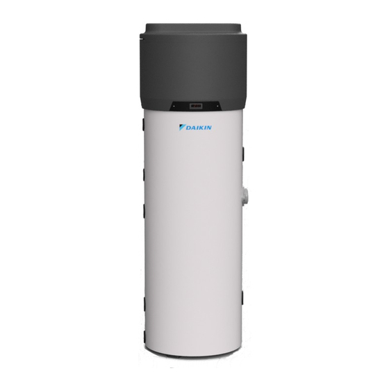
Daikin EKHH2E200AAV3 Installation Manual

Daikin EKHH2E200AAV3 Installation Manual

Domestic hot water heat pump monobloc type
Hide thumbs Also See for EKHH2E200AAV3:

Advertisement

Service
Manual
EKHH2E200AAV3(3)
EKHH2E260AAV3(3)
EKHH2E260PAAV3(3)

Installation manual

Domestic Hot Water Heat Pump
Domestic Hot Water Heat Pump - Monobloc type
4P509215-1
Monobloc type
Installation manual
Language
Language
Language
Language
Language
English

Advertisement

Table of Contents
loading

Summary of Contents for Daikin EKHH2E200AAV3

  • Page 1: Installation Manual

    4P509215-1 Installation manual Service Domestic Hot Water Heat Pump Manual Monobloc type Installation manual English Domestic Hot Water Heat Pump - Monobloc type Language Language Language EKHH2E200AAV3(3) Language EKHH2E260AAV3(3) EKHH2E260PAAV3(3) Language...
  • Page 2: Table Of Contents

    LIST OF CONTENTS 11 Disposal ............... 39 12 Unit fiche ..............40 General safety precautions .......... 5 About the documentation ..........5 1.1.1 Meaning of warnings and symbols .... 5 For the user ................ 5 For the installer ..............6 1.3.1 General .............
  • Page 3 Version Log Version code Description Date 4P509215-1 Document release 20/12/2017...
  • Page 4 Page 4 20/12/2017 - Version 1.0...
  • Page 5: General Safety Precautions

    1 General safety Symbol Explanation precautions Before installation, read the installation and operation manual, and the wiring instruction sheet. About the documentation Before performing maintenance and service tasks, read the service  The original documentation was written in English. manual. All other languages are translations.
  • Page 6: For The Installer

    Name, address and day and night telephone Make sure installation, testing and applied materials numbers for obtaining service comply with applicable legislation (in addition to the instructions described in the Daikin In Europe, EN378 provides the necessary guidance for documentation). this logbook.
  • Page 7: Refrigerant

    1.3.3 Refrigerant WARNING If applicable. Consult the installation manual of your Make sure there is no oxygen in the system. application for more information. Refrigerant may only be charged after performing the leak test and the vacuum drying. WARNING  During tests, NEVER pressurize the unit with a In case re-charge is required, consult the pressure higher than the allowed maximum...
  • Page 8: Electrical

    leakage protector. 1.3.5 Electrical DANGER: RISK OF ELECTROCUTION NOTICE  Precautions when laying power wiring: Turn OFF all power supply before removing the switch box cover, connecting electrical  Do not connect wiring of different wiring or touching electrical parts. thicknesses to the power terminal block ...
  • Page 9: Glossary

    Optional equipment Equipment made or approved by Daikin that can be combined with the unit according to the instructions in the accompanying documentation. Field supply...
  • Page 10: Introduction

    Information on safety translate or record these user instructions on memory equipment, either in whole or in part, without prior authorisation of Daikin. Any breaches shall be subject to the payment of compensation for any damage caused. All rights are reserved,...
  • Page 11: Available Versions And Configurations

    (*) Note: at Daikin’s discretion, the type of packaging IV-I: The liquid coolant passes through the lamination may be subject to change. valve, it undergoes a sudden drop in both pressure...
  • Page 12 Positions permitted for transporting and handling: Positions that are not permitted for transporting and handling purposes: √ √ WARNING! During the unit handling and installation stages, it is forbidden to put the upper part of the device under any kind of stress whatsoever due to the fact that it is not of a structural nature.
  • Page 13: Construction Characteristics

    4 Construction characteristics Heat pump. Control panel. Enclosure in embossed ABS. Steel tank (boiler) enamelled according to UNI standards (capacity: 200; 260 litres). Upper boiler thermistor. Lower boiler thermistor. Coolant recharge. Ambient air recirculation fan. Lamination valve. High-efficiency finned evaporator. The quantity of fluid inside is regulated by an appropriate thermostatic valve.
  • Page 14: Technical Characteristics

    Technical characteristics 1.9 kW Descriptions u.m. EKHH2E200AAV3(3) EKHH2E260AAV3(3) EKHH2E260PAAV3(3) HP thermal power yield 1.82 1.82 1.82 Total thermal power Heating time ( 8:17 10:14 10:14 Heating time in BOOST mode ( 3:58 5:06 5:06 Thermal losses ( Electrical data Power supply...
  • Page 15 Nominal air capacity 350÷500 Max. pressure head available Motor protection Internal thermal circuit breaker with automatic reset Condenser Wrapped externally, not in contact with water Coolant R134a Load Water storage Water storage nominal capacity Max. quantity of hot water that can be used Vmax ( Coil for connection to solar thermal 1.0 m...
  • Page 16: Important Information

     2011/65/UE Directive on the restrictions of use of certain hazardous substances in electric and Daikin shall not be held responsible under any circumstances in the event that the equipment electronic equipment (RoHS); is used for other purposes than for which it has ...
  • Page 17: Installation And Connections

    Fig. 2 – Minimum spaces An alternative solution is illustrated in Fig. 4 and 5, where a second duct draws air in from outside instead of directly from inside the premises. Model EKHH2E200AAV3(3) EKHH2E260AAV3(3) EKHH2E260PAAV3(3) Moreover, the premises must: ...
  • Page 18 Carry out the installation of each air duct making sure In order to avoid the formation of condensate: that: insulate the air discharge pipes and the air duct cover connections with steam-tight  Its weight does not adversely affect the equipment thermal cladding of an adequate thickness.
  • Page 19: Particular Installation Conditions

    Device mounting and 6.2.1 Particular installation connection conditions The device must be installed on a stable, flat floor One of the peculiarities of the system is that it can surface that is not subject to vibration. cause a considerable lowering of the air temperature of the home.
  • Page 20: Water Supply Connections

    The illustration in Fig. 8 is an example of a water supply D connection.  1714 1101     P    337,5 Water supply connections  Connect the cold water inlet and the outlet pipes to the appropriate connection points (Fig.7).
  • Page 21: Condense Drain Connections

    N.B. The safety equipment for protection against over pressure must be operated regularly in order to remove limescale deposits and to check Ø20 that it is not blocked (Fig. 8a) N.B. To ensure proper installation of the equipment, a hydraulic safety group in accordance to UNI EN 1487:2002 standard should be provided.
  • Page 22: Solar Power System Integration

    Electrical connections Solar power system integration The device is wired for the mains power supply. It is powered through a flexible cable and a socket/plug Fig. 10 is an example of solar power system integration. combination, as illustrated in Fig. 11 and Fig. 12. The connection to the mains power supply requires an earthed Schuko socket with separate protection.
  • Page 23: Wiring Diagram

    The upper cover of the boiler needs to be removed in 6.6.1.1 Remote link mode order to access the 4-core cable for remote connection (see paragraph 9.1 Fig. 18). Next, roll The equipment is provided with an additional 4-core the cable out through the appropriate opening in cable that is linked to the circuit board of the user the back cover, as indicated in Fig.
  • Page 24: Commissioning

    7 Commissioning WARNING! Make sure that the equipment is connected to the earth cable. WARNING! Make sure that the line voltage corresponds to the voltage indicated on the equipment identification plate. The commissioning procedure should be completed by following these steps: ...
  • Page 25: Operation And Use

    8 Operation and use When the equipment is switched on, it shows The setting up of the device is assigned to a user the status it was previously switched off interface that enables the:  Setting of the operating mode; 8.1.1.2 The [SET] key ...
  • Page 26: Operating Logic

     Alarm LED If lit: check the list of alarms ANTI-LEGIONELLA operating mode and follow the This function is used as an anti-bacterial treatment procedure indicated in by increasing the temperature of the water to this manual 60°C. This function is periodically and, in any case, automatically enabled every 30days, regardless of Degree Celsius If lit: the unit of measurement...
  • Page 27 If the keyboard is locked, it will be impossible to carry out any kind of operation on the display interface. 8.1.3.2 Change of operating mode (AUTOMATIC, ECONOMY and By pressing any key, “Loc” will appear for 1 OVERBOOST) second on the display. 8.1.3.2.1 AUTOMATIC operating mode To manually start the AUTOMATIC mode, follow this...
  • Page 28 N.B. 8.1.3.7 Display of the operating status Before proceeding with the timeslot settings,  set day and real time as described in Make sure that the keyboard is not locked paragraph 8.1.3.14. (paragraph 8.1.3.3) and that no other advanced procedures are in progress; To start the procedure: ...
  • Page 29 Solutions: - Check how clean the filter is (to switch off the In case of “UtL” alarm (fault of the fan), in alarm message, press any key on the display) addition to the display visualization, the equipment emits an acoustic signal that can Probable fan fault be switched off pressing any key on the user interface.
  • Page 30 8.1.3.13 Defrosting 8.1.3.14 Day and real time settings  Defrosting is enabled: Make sure that the keyboard is not locked (paragraph 8.1.3.3) and that no other advanced  Automatically, when the temperature of the procedures are in progress; evaporator is below the temperature established in ...
  • Page 31 8.1.3.15 Configuration parameter settings 8.1.3.16 Restoring default factory settings To configure parameter settings: To restore default factory settings:  Make sure that the keyboard is not locked  Ensure that the keyboard is not locked (paragraph (paragraph 8.1.3.3) and that no other advanced 8.1.3.3) and that no other advanced procedures procedures are in progress;...
  • Page 32: Particular Operations

    Particular operations The unit has a fan speed control system that increases the speed of the fan when the ambient temperature is lower than -1°C. At higher temperatures, the fan operates at a lower speed to reduce the noise of the equipment.
  • Page 33: List Of Equipment Parameters

    8.2.1 List of equipment parameters Parameter description Code U.M. Default Notes Function reserved for Password (shadow) specialised technical staff H2O Set HOT economy cycle °C/°F 55.0 H2O Set HOT automatic cycle °C/°F 55.0 45.0 H2O Set COLD °C/°F 10.0 H2O Set for heat pump stop °C/°F 70.0 62.0...
  • Page 34 Parameter description Code U.M. Default Notes Delay in equipment start-up Delay as from last ON Compressor protections Delay as from last OFF Minimum ON time Number of compressor operating hours 9999 1000 0 = Function excluded required for maintenance Delay air temperature sample taking for cold evaporator test Minimum delay between fan start-up and compressor activation for incoming air...
  • Page 35 Parameter description Code U.M. Default Notes 0 = Input disabled Solar thermal input enabling ---- 1 = Pressure input (Digital 1) 2 = Digital 1 input 0 = Active if contact is closed Type of solar thermal input contact ---- 1 = Active if contact is open High/low pressure end compressor protection...
  • Page 36 Parameter description Code U.M. Default Notes RESERVED ---- Page 36 20/12/2017 - Version 1.0...
  • Page 37: Maintenance And Cleaning

    9 Maintenance and cleaning WARNING! Any equipment repair must be performed by qualified personnel. Improper repairs can put the user in serious danger. If your equipment Click requires repair, please contact the technical assistance service. WARNING! Before attempting any maintenance operation, make sure that the equipment is not and cannot be accidentally connected to the power supply: disconnect the equipment...
  • Page 38: Quarterly Inspections

    Quarterly inspections Magnesium anodes The magnesium anode (Mg), also "sacrificial" anode,  Visual inspection of the general conditions of the avoids any parasitic currents, generated inside the equipment systems as well as the absence of boiler, that can trigger corrosion processes on the leaks;...
  • Page 39: List Of Contents 11 Disposal

    10 Troubleshooting 11 Disposal In case of issues with equipment performance, that occur without the generation of any of the alarms or At the end of their device lifecycle, the heat pumps will errors described in the relative paragraphs, it is be disposed of in conformity with the applicable recommended to check the table with possible regulations.
  • Page 40: Unit Fiche

    12 Unit fiche Descriptions u.m. EKHH2E200AAV3(3) EKHH2E260AAV3(3) EKHH2E260PAAV3(3) Declared load profile Water heating energy efficiency class under average climate conditions Water heating energy efficiency in % under average climate conditions Annual electricity consumption in kWh under average climate 1323 1323...
  • Page 42 Nov-17 Page 42 20/12/2017 - Version 1.0...

Table of Contents