Table of Contents

Related Manuals for Phoenix BigSound PB17

Summary of Contents for Phoenix BigSound PB17
- Page 1 BigSound™ PB17 Handbook Phoenix Sound Systems, Inc. 3514 West Liberty Road Ann Arbor MI 48103 www.phoenixsound.com phone: +1 (800) 651-2444 fax: +1 (734) 662-0809 e-mail: phoenixsound@phoenixsound.com ©2018 Phoenix Sound Systems, Inc.
-
Page 2: Table Of Contents
Table of Contents Introduction........................3 Getting Acquainted......................4 Changes in the PB17....................4 The Sound Board Connectors..................5 Initial Checkout.........................6 The Basic Bench Test....................6 Trigger Checkout.......................7 Reed Switch Speed Checkout..................7 Other Trigger Checkout....................7 Default Trigger Assignments..................7 Standard Sounds and Effects.....................8 All Systems.........................8 Diesel Systems......................8 Steam Systems......................8 Triggered Sounds and Effects....................9 All Systems.........................9... -
Page 3: Introduction
Introduction Dear Model Railroading Friends, Thank you for choosing Phoenix Sound Systems to fill your railroad with sound. The PB17system maintains and expands on the abilities of the PB9, adding a fifth trigger input and increased battery charging efficiency. The PB17 will run on DC, DCC, Battery –... -
Page 4: Getting Acquainted
Getting Acquainted Changes in the PB17 The PB17 sound board is electrically identical to the original PB11 board. We know there will be some unavoidable confusion. The main difference to note is the return of screw terminals. We have also returned the line level audio output to the P1 terminal block. -
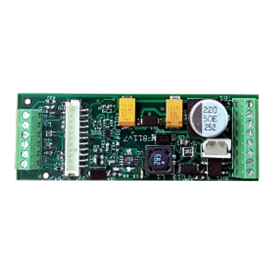
Page 5: The Sound Board Connectors
The Sound Board Connectors Terminal Purpose Terminal Purpose Power/DCC Trigger Ground Power/DCC Trigger Input 1 [Volume] Ground Trigger Input 2 Volume Level Trigger Input 3 [Volume] +5V Trigger Input 4 Audio Line Level Out Trigger Input 5 Speaker Speaker Connector: Pin Purpose Color Termination... -
Page 6: Initial Checkout
Initial Checkout The Basic Bench Test Each system is tested before shipping but we recommend that you hook things up on your workbench, play with the system and get comfortable with the components before installation. The power supply connects to Terminals 1 & 2. A power source of any polarity is acceptable. -
Page 7: Trigger Checkout
Trigger Checkout Reed Switch Speed Checkout In order for steam to leave the idle state you will need a reed switch connected to terminals 13 & 14; you may wish to hook one up and experiment with the magnets to get an idea of the sensitivity of reed switches. This will help you decide how to mount them in the locomotive or car. -
Page 8: Standard Sounds And Effects
Standard Sounds and Effects Most sounds play automatically based on train speed. Many sounds can also be set to play using designated trigger inputs. The following section describes the standard sound system configuration. All Systems Whistle/Horn: Toots when starting (2 forward, 3 reverse) and stopping (one toot). -
Page 9: Triggered Sounds And Effects
Triggered Sounds and Effects The PB17 board has five trigger inputs. The Auxiliary Input Board [P5T] allows you to trigger additional sounds using reed switches or outputs from remote control receivers. The following section describes sounds which may be assigned to triggers or DCC functions. Of course, any sound can be assigned to a trigger. -
Page 10: Adjusting Settings Without A Pc
Adjusting Settings Without a PC All of the following adjustments can be more easily made using the Phoenix Computer Interface. You can still do a great deal of configuration without the Computer Interface. The functions that can be configured without the interface... -
Page 11: Option Selection Example: Steam Speed From Voltage
Option Selection Example: Steam Speed from Voltage Connect together terminals P4:1 and P4:3. This can be easily done by inserting a 2.5mm MONO plug (“shorting plug”) into the access jack. Remove ALL wires from terminals 9-13. This will select all the options in the “Open”... -
Page 12: Start Voltage Adjustment
Start Voltage Adjustment If you ordered a sound system to match your locomotive you can usually skip this step. The Starting Voltage is the voltage at which the train begins to move and the sound changes from idle to running. In trigger mode there are some sounds that play based upon the starting voltage, even though voltage does not determine speed. -
Page 13: Dcc
DCC Checkout The sound board default address is 3. Connect the sound board to your DCC source. Select address 3 on your DCC controller. Turn the speed up and down, sounds should play in coordination with the changing speed commands. Test the function buttons, the default function assignments are listed in the chart below. -
Page 14: Control Variables (Dcc Cv)
Control Variables (DCC CV) The PB17firmware supports the following Control Variables. These can be programmed on the program track (service mode) or on the main (ops mode – see note below). (“P ”) MODE ROGRAMMING ON THE IS NOT RECOMMENDED FOR ADDRESS CHANGE COMMANDS CV Description Default Value... -
Page 15: Installation Guidelines
Installation Guidelines Speaker – Use the largest speaker that can reasonably fit your available space. For best acoustics, the speaker should be sealed to the floor so that sound going out the front of the speaker cannot easily get to the back side. Volume Switch and Access Jack –... -
Page 16: Troubleshooting
Troubleshooting Wrong directional toots – Swap wires between Terminals 1 & 2 or change the track polarity using the Computer Interface. No Sound – Start by rechecking the wiring to the speaker, volume switch, and power connector. A connection may have been missed or become loose. Measure the voltage applied to the power connector when you think the board should be on. -
Page 17: Technical Specifications
Technical Specifications Length – 2.56 in; 65.15 mm Width – 0.93 in ; 23.6 mm Height – 0.5 in ; 12.7 mm Maximum Track Volts – 30V. Max Battery Input (C3) Volts – 30V. Power Consumption – Varies with volume; can go as high as 1000mA if at max volume;... -
Page 18: Appendix A: Wiring Diagrams
Appendix A: Wiring Diagrams Common Symbol Key Diode Computer Access Jack Volume Switch Reed Switch Loudspeaker January 2018 - 18 -... -
Page 19: Basic Dc
Basic DC Track 3.6V Battery Bell Trigger Whistle Trigger Speed Trigger January 2018 - 19 -... -
Page 20: Basic Dcc
Basic DCC Track Speed Trigger January 2018 - 20 -... -
Page 21: Cvp Airwire 900 G3
CVP Airwire 900 G3 Main Battery Speed Trigger January 2018 - 21 -... -
Page 22: Aristocraft/Crest Revolution
Aristocraft/Crest Revolution DDITIONAL WIRING DIAGRAMS FOR BATTERY POWERED NON PLUG AND PLAY LOCOMOTIVES AS WELL AS TRACK AND BATTERY POWERED LOCOMOTIVES EQUIPT WITH THE PLUG AND PLAY SOCKET CAN BE FOUND IN THE PHOENIX SOUND ONLINE KNOWLEDGEBASE AT HTTP PHOENIXSOUND... -
Page 23: Locolinc
Locolinc® 3.6V Battery Power In: Main Battery Track or Battery Bell Speed Trigger Horn/Whistle January 2018 - 23 -... -
Page 24: G Scale Graphics Railboss 4
G Scale Graphics RailBoss 4 Main Battery Bell Horn/Whistle Speed Trigger January 2018 - 24 -... -
Page 25: Basic Ride On
Basic Ride On Bell Trigger Horn Trigger Speed Trigger 12V Batt 12V Batt Motor Controller Auxiliary Amplifier .1 uF 1N4001 or equivalent Note 1: *OPTIONAL* Note 2: If not hooking to an electric 0.1 uF cap will start the board motor move the battery wires to when battery is turned on. -
Page 26: Appendix B: The Computer Interface
The Computer Interface consists of a CD and USB Interface for use with Windows 2000, XP and Vista. The CD contains software to customize sounds from the Phoenix Sound library. Connecting the USB interface to the board through the access jack allows you to download sounds for different engines and... -
Page 27: Warranty
A service fee may be assessed if it is determined that the failure was not due to any Phoenix supplied components. Phoenix Sound Systems, Inc. cannot be liable for damage to the system during shipping to our facilities due to mishandling, inadequate packaging or similar circumstances beyond our control.
Need help?
Do you have a question about the BigSound PB17 and is the answer not in the manual?
Questions and answers