Table of Contents
Advertisement
TERASAKI ELECTRIC (EUROPE) LTD.
80 Beardmore Way, Clydebank Industrial Estate,
Clydebank, Glasgow, G81 4HT, Scotland (UK)
Telephone: 44-141-941-1940
Fax:
44-141-952-9246
Email:
marketing@terasaki.co.uk
http://www.terasaki.com
TERASAKI MIDDLE EAST
Saif Zone Q3-168, PO Box 120860
Sharjah, UAE
Telephone: 971-56-676-4825
Fax:
976-655-78141
Email:
middleeast@terasaki.co.uk
http://www.terasaki.com
TERASAKI ELECTRIC (EUROPE) LTD.
(FILIALE ITALIA)
Via Ambrosoli, 4A-20090, Rodano, Milano, Italy
Telephone: 39-02-92278300
Fax:
39-02-92278320
Email:
info@terasaki.it
http://www.terasaki.it
TERASAKI ELECTRIC (EUROPE) LTD.
(SUCURSAL EN ESPAÑA)
Pol. Ind. Coll de la Manya, C/Cal Ros dels Ocells 5
08403 Granollers , (Barcelona) España
Telephone: 34-93-879-60-50
Fax:
34-93-870-39-05
Email:
terasaki@terasaki.es
http://www.terasaki.es
TERASAKI ELECTRIC (EUROPE) LTD.
(FILIAL SVERIGE)
Snickarvägen 2, SE-132 38 SALTSJÖ-BOO, Sweden
Telephone: 46-8-556-282-30
Fax:
46-8-556-282-39
Email:
info@terasaki.se
http://www.terasaki.se
TERASAKI CIRCUIT BREAKERS (S) PTD. LTD.
17 Tuas Street, Singapore, 638454
Telephone: 65-6744-9752
Fax:
65-6748-7592
Email:
tecs@pacific.net.sg
TERASAKI ELECTRIC CO., LTD.
Head Office & Circuit Breaker Division
6-13-47 Kamihigashi, Hirano-ku,
Osaka 547-0002, Japan
Telephone: 81-6-6791-2763
Fax:
81-6-6791-2732
Email:
int-sales@terasaki.co.jp
http://www.terasaki.co.jp
TERASAKI ELECTRIC (M) SDN, BHD.
Lot 3, Jalan 16/13D, 40000 Shah Alam,
Selangor Darul Ehsan, Malaysia
Telephone: 60-3-5549-3820
Fax:
60-3-5549-3960
Email:
terasaki@terasaki.com.my
TERASAKI DO BRASIL LTDA.
Rua Cordovil, 259-Parada De Lucas,
21250-450, Rio De Janeiro-R.J., Brazil
Telephone: 55-21-3301-9898
Fax:
55-21-3301-9861
Email:
terasaki@terasaki.com.br
http://www.terasaki.com.br
TERASAKI ELECTRIC (CHINA) LTD.
72 Pacific Industrial Park, Xin Tang Zengcheng,
Guangzhou 511340, China
Telephone: 86-20-8270-8556
Fax:
86-20-8270-8586
Email:
terasaki@public.guangzhou.gd.cn
TERASAKI ELECTRIC GROUP SHANGHAI
REPRESENTATIVE OFFICE
Room No. 1405-6, Tomson Commercial Building,
710 Dong Fang Road, Pudong, Shanghai,
200122, China
Telephone: 86-21-58201611
Fax:
86-21-58201621
Email:
terasaki@vip.163.com
Advertisement
Table of Contents

Related Manuals for TERASAKI TemPower 2

Summary of Contents for TERASAKI TemPower 2
- Page 1 Snickarvägen 2, SE-132 38 SALTSJÖ-BOO, Sweden 710 Dong Fang Road, Pudong, Shanghai, Telephone: 46-8-556-282-30 200122, China Fax: 46-8-556-282-39 Telephone: 86-21-58201611 Email: info@terasaki.se Fax: 86-21-58201621 http://www.terasaki.se Email: terasaki@vip.163.com TERASAKI CIRCUIT BREAKERS (S) PTD. LTD. 17 Tuas Street, Singapore, 638454 Telephone: 65-6744-9752 Fax: 65-6748-7592 Email: tecs@pacific.net.sg...
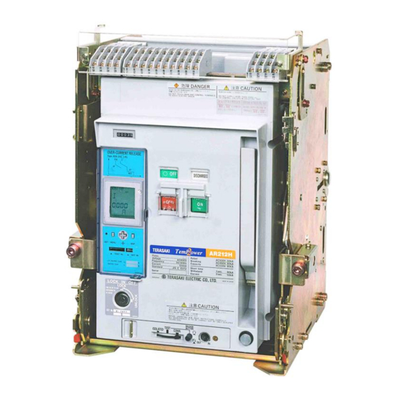
- Page 2 INSTRUCTION MANUAL FOR AIR CIRCUIT BREAKERS (With Draw-out Cradle and Type AGR-11B,21B,22B,31B Overcurrent Protective Device) Types: AR208S AR212S AR216S AR220S AR325S AR332S AR440S AR440SB AR212H AR216H AR220H AR316H AR320H AR325H AR332H AR420H AR440H AR208D AR212D AR216D Notice Be sure to read this manual before installing, operating, servicing, or inspecting the ACB. ...
-
Page 4: Table Of Contents
TABLE OF CONTENTS 5-3-2-1. General 1. SAFETY NOTICES 5-3-2-2. Available screens 2. RECEIVING AND HANDLING 5-3-2-3. Monitor screen 2-1. Transportation Precautions 5-3-2-3-1. Monitor screen (AGR-21B,22B) 2-1-1. Transporting the ACB 5-3-2-3-2. Monitor 1 screen (AGR-31B) 2-1-2. Transporting the breaker body 5-3-2-3-3. Monitor 2 screen (AGR-31B) 2-1-3. - Page 5 KRB-5404...
-
Page 6: Safety Notices
1. SAFETY NOTICES Thank you for purchasing the TERASAKI AR-series Air Circuit Breaker (TemPower2). This chapter contains important safety information. Be sure to carefully read these safety notices, instruction in this manual, and other documents accompanying the Air Circuit Breaker (hereinafter referred to as the ACB) to familiarize yourself with safe and correct procedures or practices before installing, operating, or servicing the ACB. - Page 7 Operation Precautions (continued) CAUTION Repeated open/close operation by the motor charging mechanism without pause should not exceed 15 times. If repeated continuous open/close operation is inevitable, a pause of at least 20 minutes should be provided after the repetitions of 15 times.
-
Page 8: Receiving And Handling
2. RECEIVING AND HANDLING Upon receipt of your ACB, check the following. If you have any question or problem, contact us at the indicated on the back cover of this manual. Check that the ACB received is as ordered and that the accessories are as specified. ... -
Page 9: Transporting The Breaker Body
2-1-2. Transporting the breaker body Use an optional lifter or lifting plate to transfer the breaker body. When transporting the breaker body on a lifter, move the lifter with the lifter fork held at the lowest possible position. ... -
Page 10: Installation Precautions
2-3. Installation Precautions CAUTION Electrical work must be done by competent persons. Do not place the ACB in such an area that is subject to high temperatures, high humidity, dusty air, corrosive gases, strong vibration and shock, or other unusual conditions. Mounting the ACB in such an area could cause a fire or malfunction. ... - Page 11 Do not install the ACB in such an area that is exposed to direct sunlight. Make sure that the mounting base has a sufficient capacity of bearing the weight of the ACB (see Table 3 and Table 4). The mounting base must be protected against vibration.
- Page 12 Connect conductors to the main circuit terminals in the conductor connection area as shown in Figs. 6 - 9. Vertical terminals, 3 Poles Vertical terminals, 4 Poles Right side view Back view Right side view Back view ...
- Page 13 Vertical terminals, 3 Poles Vertical terminals, 4 Poles Right side view Back view Right side view Back view Horizontal terminals, 3 Poles Horizontal terminals, 4 Poles Right side view Back view Right side view Back view ...
- Page 14 Vertical terminals, 3 Poles Right side view Back view Vertical terminals,4 Poles Right side view Back view Fig. 8 Conductor (include screw) connection area (AR440S) *Insulation distance of conductor connection area and earth metal is more than 12.5mm. KRB-5404...
- Page 15 ●Vertical terminals, 3 Poles Right side view Back view ●Vertical terminals, 4 Poles Right side view Back view Fig. 9 Conductor (include screw) connection area (AR440SB) *Insulation distance of conductor connection area and earth metal is more than 12.5mm. Use a support to hold conductors securely at distance L as shown in Fig.
- Page 16 The following procedure makes it easy to make connections with plug-in tab terminals (#187) of position switches, control circuit terminals, and auxiliary switches. (1) Draw out the breaker body to the removed position, and remove it using an optional lifter or lifting plate. Refer to sections 4-2-2 and 2-1-2.
-
Page 17: General
*7: Applicable to 3-pole ACBs with INST or MCR. *8: For applicability to power distribution IT systems, consult us *9: A special version of the breaker is available to use above 250V DC. Contact Terasaki for details. *10: For AC500V *11: Expected service life based on endurance test. - Page 18 *8: For applicability to power distribution IT systems, consult us *10: A special version of the breaker is available to use above 250V DC. Contact Terasaki for details. *11: Expected service life based on endurance test. The service life of ACB depends on the working and environmental conditions. Refer to chapter 6 “Maintenance, Inspection and Parts Replacement”.
- Page 19 *9: For applicability to power distribution IT systems, consult us *10: A special version of the breaker is available to use above 250V DC. Contact Terasaki for details. *11: Expected service life based on endurance test. The service life of ACB depends on the working and environmental conditions. Refer to chapter 6 “Maintenance, Inspection and Parts Replacement”.
- Page 20 Table 6 shows the dielectric withstand voltage and the insulation resistance of the ACBs. CAUTION Do not perform dielectric withstand/insulation resistance tests under other conditions than specified. Doing so may cause a malfunction. Table 6 Dielectric withstand voltage and insulation resistance Insulation Impulse withstand resistance...
-
Page 21: Parts And Functions
3-2. Parts and Functions Fig. 14 provides a general views of the ACB. ◯ ON-OFF indicator Front cover ◯ ◯ Charge indicator ON-OFF cycle counter ◯ OFF button ◯ ◯ Charging handle ON-OFF button cover ◯ Lock-in-OFF plate ◯ ◯ ON button ◯... - Page 22 ◯ Consists of breaker body ◯ and draw-out cradle ◯ Comes with main circuit terminals ◯ , control circuit terminals ◯ , auxiliary switches ◯ ◯ Draw-out cradle and position switches ◯ Contains the ON-OFF mechanism, the closing coil,the tripping device, and overcurrent ◯...
- Page 23 Control circuit Allow connections of external control wire to the control circuits. Wire connections are ◯ terminals made through M4 screw terminals. Fig. 15 shows the control circuit terminals. Fig. 15 Control circuit terminals Control terminal Protects the position switches, the control circuit terminals and the auxiliary switches from ◯...
- Page 24 White paper KRB-5404...
-
Page 25: Circuits And Ratings
3-3. Circuits and Ratings Fig. 17 shows an ACB(AGR-11B) circuit diagram and Table 9 and Fig. 18 show the function of each terminal and the meaning of each sign in the diagram. Fig. 17-1 Breaker circuits 1 Table 9-1 Terminal functions and circuit symbols 1 (Applicable to both 50 and 60Hz for AC. ◯ and ◯... - Page 26 *9: Do not use these terminals for other circuits when both instantaneously rated shunt trip and UVT are fitted. These terminals are used by Terasaki as the anti- burnout SW for the instantaneously rated shunt trip.
- Page 27 Fig. 19 shows an ACB(AGR-21B,22B,31B) circuit diagram and Table 10 and Fig. 18 show the function of each terminal and the meaning of each sign in the diagram. AGR-21B,22B,31B Fig. 19-1 Breaker circuits 1 and ◯ Table 10-1 Terminal functions and circuit symbols 1(Applicable to both 50 and 60Hz for AC. ◯ mean the polarity for DC) Function Terminal No.
- Page 28 *10: Do not use these terminals for other circuits when both instantaneously rated shunt trip and UVT are fitted. These terminals are used by Terasaki as the anti- burnout SW for the instantaneously rated shunt trip.
- Page 29 Fig. 20 provides the terminal arrangement of the ACB. Position switches Auxiliary switches (When 4C is used) (When standard 4C + optional 6C are used) Upper stage Middle stage Lower stage (When 2C is used) (When standard 4C is used) Upper stage Middle stage Lower stage...
- Page 30 Tables 11 - 16 show the ratings of the operation power supply, the shunt trip device (SHT), the undervoltage trip device (UVT), auxiliary switches, position switches, operation indication contacts, and the N-phase CT. Table 11 Ratings of operation power supply Ratings of operation power supply Permissible Rated voltage...
- Page 31 Table 14 Ratings of auxiliary and position switches Auxiliary switches *1 *2 Position switches For general feeder For microload *3 Voltage (V) Inductive load (A) Inductive load (A) Inductive load (A) Resistive load (A) Resistive load (A) Resistive load (A) AC100 - 250 AC251 - 500 DC30...
-
Page 32: Operation
4. OPERATION 4-1. Charging and Opening operation DANGER Never touch live terminal parts. Otherwise, electric shock may result. CAUTION Do not force down the charging handle after completion of manual charging operation. Doing so may cause a malfunction. ... -
Page 33: Closing Operation
Motor charging ) changes to “DISCHARGED” while the specified operation voltage is applied to the control When the charge indicator (Fig. 23 ◯ circuit terminals □ and □ , the charging motor is activated to start charging the closing springs. Upon completion of the charging operation, the charge indicator shows “CHARGED”... -
Page 34: Motion Of Operation Mechanisms
4-1-5. Motion of operation mechanisms Figs. 24 - 27 illustrate the motion of the charging and ON-OFF mechanisms. For manual closing operation, ON button ◯ rotates counterclockwise. For electrical closing operation, ◯ ◯ push rod ◯ ' protrudes downward from the latch release coil (LRC) and charge latch trigger ◯... - Page 35 ◯ The charging handle or the charging motor provides a counterclockwise rotation to charging cam ◯ . This rotates closing release lever ◯ and closing tripper ◯ lever ◯ counterclockwise and a semicircular pawl engages with closing release lever ◯ .
-
Page 36: Draw-Out And Insertion Operation
4-2. Draw-out and Insertion Operation 4-2-1. General The draw-out type ACB consists of the breaker body and the draw-out cradle. The main and control circuit terminals are installed on the draw-out cradle, which permits you to draw out and inspect or service the breaker body without the need for removing wiring from the terminals. -
Page 37: Draw-Out Operation
4-2-2. Draw-out operation DANGER Never touch live terminal parts. Otherwise, electric shock may result. Do not leave the ACB body in the removed position. The weight of the ACB may cause serious injury. CAUTION If the ACB has the breaker fixing bolts, be sure to loosen the bolts on both sides before draw-out operation. Otherwise, damage to the ACB may result. -
Page 38: Putting The Breaker Body Back Into The Draw-Out Cradle
4-2-2-2. Moving the breaker body from the TEST position to the ISOLATED position 1) Open the ACB. (If the ACB remains closed, the draw-out handle (Fig. 29 ◯ ) cannot be inserted). 2) Press the release button (Fig. 29 ◯ ). - Page 39 4) Make sure the breaker fixing bolts (Fig. 29 ◯ ), if fitted, are loosened and not arrest the breaker body. 5) Make sure the hand connector (Fig. 29 ◯ ) of the communication terminal block, if fitted, is so positioned that it does not get caught between the breaker body and the draw-out cradle.
-
Page 40: Contact Status Of Auxiliary And Position Switches
4-2-4. Contact status of auxiliary and position switches Tables 18 and 19 show the contact status of auxiliary switches and position switches respectively. Table 18-1 Contact status of auxiliary switches ACB state Status of Status of Breaker a-contact b-contact body position CONN. -
Page 41: Lock In Off Procedure
4-4. Lock in OFF Procedure 1) Open the OFF button cover shown in Fig. 33. 2) Raise the OFF-lock tab and close the button cover. 3) Lock the button cover using a padlock with ø6 shackle (up to 3 padlocks can be used) as shown in Fig. 33. The OFF button is locked depressed, which disables the ON button. -
Page 42: Breaker Fixing Bolt Securing Procedure
4-6. Breaker Fixing Bolt Securing Procedure 1) Move the breaker body to the CONN. position. 2) Loosen the breaker fixing bolt shown in Fig. 35, move the spring and flat washers close to the bolt head and push the bolt into the U-notch of the grip. -
Page 43: Overcurrent Release (Ocr)
5. OVERCURRENT RELEASE (OCR) Options available for the type AR ACBs include a highly reliable, multi-functional overcurrent release (OCR) with a built-in 16-bit microprocessor. This OCR is supplied with power through a CT and main circuit current signals from current sensors. When the OCR detects a fault, it sends a trip signal to the magnet hold trigger (MHT) or provides a trip indication or an alarm depending on the type of the fault. - Page 44 Table 21 Specifications of type AGR-21B, 22B, 31B OCR (: Standard, : Optional, –: Not applicable) Application For general feeder For generator protection Characteristic AGR- AGR- AGR- AGR- AGR- XXXX - AGR- Reference Type designation 21BL-XX 31BL-XX 21BR-XX 31BR-XX 31BS-XX section 21BS 22BS...
-
Page 45: Characteristics
5-2. Characteristics 5-2-1. L characteristic for general feeder A general view, characteristic settings, and characteristic curves of the type AGR-11BL OCR (with L characteristic) are shown in Fig. 37, Table 22, and Fig. 40 respectively. ◯ ◯ ◯ ◯ ◯ ◯... - Page 46 Characteristic settings and characteristic curves of the type AGR-21BL, 31BL OCR (with L characteristic) are shown in Table 23 and Fig. 38-40 respectively. Table 23 Settings of type AGR-21BL,31BL OCR (with L characteristic) Setting range ○ Setting item Symbol CT rated primary current [I ] ×...
- Page 47 Long time delay trip, Short time delay trip, Instantaneous trip N-phase protection trip and Pre-trip alarm Negative-phase sequence protection Ground fault trip Fig. 40 Characteristic curves of type AGR-11BL,21BL,31BL OCR (with L characteristic) KRB-5404...
-
Page 48: R Characteristic For General Feeder
5-2-2. R characteristic for general feeder Characteristic settings and characteristic curves of the type AGR-21BR,31BR OCR (with R characteristic) are shown in Table 24 and Figs. 41 - 47 respectively. Table. 24 Characteristic settings of type AGR-21BR,31BR OCR (with R characteristic) Setting item Symbol Setting range○... - Page 49 Long time delay trip, short time delay trip, instantaneous trip and pretrip alarm N-phase protection 0.02 Fig. 42 Characteristic curves of type AGR-21BR,31BR OCR (with R characteristic of I t protection type) Long time delay trip, short time delay trip, instantaneous trip and pretrip alarm N-phase protection Fig.
- Page 50 Long time delay trip, short time delay trip, instantaneous trip and pretrip alarm N-phase protection Fig. 44 Characteristic curves of type AGR-21BR,31BR OCR (with R characteristic of I t protection type) Long time delay trip, short time delay trip, instantaneous trip and pretrip alarm N-phase protection Fig.
- Page 51 Long time delay trip, short time delay trip, instantaneous trip and pretrip alarm N-phase protection Fig. 46 Characteristic curves of type AGR-21BR,31BR OCR (with R characteristic of I t protection type) Negative-phase sequence protection Ground fault trip Fig. 47 Characteristic curves of type AGR-21BR,31BR OCR (with R characteristic of common protection type) KRB-5404...
-
Page 52: S Characteristic For Generator Protection
5-2-3. S characteristic for generator protection Characteristic settings and characteristic curves of the type AGR-21BS/22BS/31BS OCR (with S characteristic) are shown in Table 25 and Figs. 48 and 49 respectively. Table. 25 Characteristic settings of type AGR-21BS,22BS,31BS OCR (with S characteristic) Setting range ○... - Page 53 Long time delay trip, short time delay trip, instantaneous trip and pretrip alarm Reverse power trip Fig. 49 Characteristic settings of type AGR-21BS/22BS/31BS OCR (with S characteristic) KRB-5404...
-
Page 54: Ocr Setting Procedure
5-3. OCR Setting Procedure 5-3-1. OCR Setting Procedure (AGR-11B type) CAUTION OCR field tests and setting changes must be performed by competent persons. After setting changes are made, the settings be checked with e.g., a type ANU-1 OCR checker (optional). ... -
Page 55: Ocr Setting Procedure (Agr-21B,22B,31B Type)
5-3-2. OCR Setting Procedure (AGR-21B,22B,31B type) CAUTION OCR field tests and setting changes must be performed by competent persons. After setting changes are made, the settings be checked with e.g., a type ANU-1 OCR checker (optional). After completion of OCR tests, be sure to return the settings to the original values. Failure to do so may cause a fire or burnout. -
Page 56: Available Screens
5-3-2-2. Available screens The type AGR-21B/22B OCR has six screens available as shown in Fig. 54 below. Press the MENU button to go to the next screen. Monitor screen (MONI): See 5-3-2-3-1. This is the initial screen that appears when control power is turned on. Various current values can be viewed on this screen. - Page 57 The type AGR-31B OCR has seven screens available as shown in Fig. 55 below. Press the MENU button to go to the next screen. Monitor 1 screen (MONI): See 5-3-2-3-2 This is the initial screen that appears when control power is turned on. Various current values can be viewed on this screen.
-
Page 58: Monitor Screen
5-3-2-3. Monitor screen 5-3-2-3-1. Monitor screen (AGR-21B,22B) Fig. 56 shows how to navigate the monitor screen and Table 26 lists the items that can be viewed on this screen. ◯ ◯ ◯ ◯ ◯ ◯ ◯ ◯ ◯ ◯ ◯ ◯... -
Page 59: Monitor 1 Screen (Agr-31B)
5-3-2-3-2. Monitor 1 screen (AGR-31B) Fig. 57 shows how to navigate the monitor 1 screen and Table 27 lists the items that can be viewed on this screen. ◯ ◯ ◯ ◯ ◯ ◯ ◯ Fig. 57 Monitor 1 screen navigation Table 27 Monitor 1 subscreens Subscreen item *1 Description... -
Page 60: Monitor 2 Screen (Agr-31B)
5-3-2-3-3. Monitor 2 screen (AGR-31B) Fig. 58 shows how to navigate the monitor 2 screen and Table 28 lists the items that can be viewed on this screen. ◯ ◯ ◯ ◯ ◯ ◯ ◯ ◯ ◯ ◯ ◯ ◯ ◯... - Page 61 ◯ (to the previous page) ◯ - ◯ (from the previous page) ◯ ◯ ◯ ◯ (to the previous page) Fig. 58-2 Monitor 2 screen navigation Table 28 Monitor 2 subscreens Subscreen item *1 Description Tolerance ○ (Monitor 1 screen) See 5-3-2-3-2.
-
Page 62: Setup Screen
5-3-2-4. Setup screen 5-3-2-4-1. Setup screen(AGR-21B,22B) Fig. 59 shows how to navigate the setup screen and Table 29 lists the items that can be viewed on this screen. ◯ ○ ◯ ◯ ◯ ◯ ◯ ◯ ◯ ◯ ◯ ◯ ◯... - Page 63 ◯ (to the previous page) ◯ - ◯ (to the previous page) ◯ ◯ ◯ ◯ ◯ ◯ Cancel Save change Setting change mode ◯ ◯ ◯ Other settings can be changed in the same way on the respective subscreens. :Flashing Fig.
-
Page 64: Setup Screen(Agr-31B)
5-3-2-4-2. Setup screen(AGR-31B) Fig. 60 shows how to navigate the setup screen and Table 30 lists the items that can be viewed on this screen. ○ ◯ × 2 ◯ ◯ ◯ ◯ ◯ ◯ ◯ ◯ ◯ ◯ ◯ ◯... - Page 65 ◯ (to the previous page) ◯ - ◯ (from the previous page) ◯ ◯ ◯ ◯ ◯ ◯ ◯ ◯ ◯ ◯ Cancel Save change Setting change mode Other settings can ◯ ◯ ◯ be changed in the same way on the respective subscreens.
- Page 66 Table 30 Setup subscreens Setting Subscreen item *1 Setting range/Remarks *2 change – ○ (Monitor 1 screen) See 5-3-2-3-2. ○ Main circuit rated voltage Disabled Fixed *3 ○ CT rated primary current Disabled Fixed *3 Determined (calculated with main circuit rated voltage and rated current [I ○...
-
Page 67: Reset Screen
5-3-2-5. Reset screen 5-3-2-5-1. Reset screen (AGR-21B,22B) Fig. 61 shows how to navigate the reset screen and Table 31 lists the items that can be cleared on this screen. When an item is cleared while its contact output is on, the contact output turns off. ◯... -
Page 68: Reset Screen(Agr-31B)
5-3-2-5-2. Reset screen(AGR-31B) Fig. 62 shows how to navigate the reset screen and Table 32 lists the items that can be cleared on this screen. When an item is cleared while its contact output is on, the contact output turns off. ◯... -
Page 69: Setting 1 Screen
5-3-2-6. Setting 1 screen Fig. 63 shows how to navigate the Setting 1 screen and Table 33 lists the items that can be viewed or changed on this screen. ’ ◯ ◯ ◯ × 3 (AGR-21B/22B) × 4 (AGR-31B) ◯ ◯... - Page 70 Table 33 Setting 1 subscreens Subscreen item *1 Setting range/Remarks *2 *3 ○ (Monitor screen) See 5-3-2-3. ○ ] × (0.5-0.63-0.8-1.0) (A) Rated current (L/R characteristic) ’ ○ Rated current (S characteristic) ] × (0.5 to 1.0) (A): Fixed to a single point in increments of 1A Long time delay trip characteristic ○...
-
Page 71: Setting 2 Screen
5-3-2-7. Setting 2 screen Fig. 64 shows how to navigate the Setting 2 screen and Table 34 lists the items that can be viewed or changed on this screen. ◯ ◯ × 4 (AGR-21B/22B) × 5 (AGR-31B) ◯ ◯ ◯ ◯... - Page 72 ◯ (to the previous page) ◯ - ◯ (from the previous page) ◯ ◯ ◯ ◯ ◯ ◯ ◯ ◯ ◯ ◯ ◯ ◯ ◯ ◯ ◯ ◯ - ◯ (from the previous page) ◯ (to the previous page) Cancel Save change ◯...
- Page 73 Table 34 Setting 2 subscreens Subscreen item *1 Setting range/Remarks *2 *3 ○ (Monitor screen) See 5-3-2-3. ○ Ground fault trip mode TRIP/AL/OFF ○ Ground fault trip pickup current ] × (0.1-0.2-0.3-0.4-0.6-0.8-1.0-NON) (A) ○ Ground fault trip pickup time 0.1-0.2-0.3-0.5-1-2 (sec) ○...
-
Page 74: Maintenance Screen
5-3-2-8. Maintenance screen Fig. 66 shows how to navigate the maintenance screen and Table 35 lists the items that can be viewed on this screen. ◯ ◯ × 5 (AGR-21B/22B) × 6 (AGR-31B) ◯ ◯ ◯ ◯ ◯ ◯ ◯ ◯... -
Page 75: Ocr Function Check
5-4. OCR Function Check CAUTION OCR function check and setting changes must be performed by competent persons. After completion of OCR tests, be sure to return the settings to the original values. Failure to do so may cause a fire or burnout. - Page 76 ◯ ◯ ◯ ◯ ◯ ◯ ◯ ◯ ◯ × 5 × 6 ◯ ◯ ◯ ◯ ◯ ◯ ◯ ◯ ◯ : Flashing ◯ Fig. 67 OCR function check screen navigation Table 37 OCR function check subscreens Subscreen item *1 Description ○...
-
Page 77: Operation Indication And Indication Resetting Procedure
5-5. Operation Indication and Indication Resetting Procedure 5-5-1. Operation Indication (AGR-11B type) The OCR has LEDs on the front panel to provide operation indications as shown in Fig. 68 and Table 38. It also outputs operation signals to contacts. (Red) ◯ Fig. -
Page 78: Operation Indication And Indication Resetting
5-5-2. Operation Indication and Indication Resetting Procedure (AGR-21B,22B,31B type) The OCR indicates a trip/alarm event on the LCD and provides contact output as shown in Table 39. Pressing the right or left key of the cross button changes the display from "trip/alarm cause" / "fault current/voltage/power" to "operating time" (if applicable). Pressing the MENU button returns the display to the previous screen. - Page 79 Table 39-2 Operation indication 2 Contact output State State After After Terminal Operation control control Normal Normal When When picked up When activated power is off power is off operation See Fig. 19 operation activated for at least for at least 1 sec.
-
Page 80: Maintenance, Inspection And Parts Replacement
Normal inspection includes inspection and actions that can be done only with removing the arc chamber, contacts, front cover and the like. Normal inspection can be performed by the user. Terasaki also provides normal inspection service. Detailed inspection includes inspection, actions, and parts replacement that will be done to prevent functional degradation caused by aging or the like when abnormality is found during normal inspection. -
Page 81: Inspection Procedures
6-1. Inspection Procedures CAUTION ACB maintenance, inspection and parts replacement must be performed by competent persons. Do not touch ACB current carrying parts and ACB structural parts close to a current carrying part immediately after the ACB trips open. Remaining heat may cause a burn. ... - Page 82 Table 42 Normal inspection procedure Check point Check item Description Discoloration Check connection conductors, main circuit terminals, and current carrying parts for heat of conductors discoloration. If such a symptom is found, contact us. Check that screws, bolts, nuts, washers, springs, retainers and the like are not missing. If any parts Parts missing General are missing, contact us.
- Page 83 Table 43 Detailed inspection procedure Check point Check item Description Disconnect hand connector (red) and, using tester, measure coil resistance between terminals and make Coil resistance sure holding coil is rated at 410 - 510 and attraction coil at 5.6 - 6.8. (*) If not so, replace UVT. Remove UVT and press in plunger, and make sure releasing plunger causes plunger to be smoothly Operation restored.
-
Page 84: Parts Replacement Procedure
6-2. Parts Replacement Procedure CAUTION ACB maintenance, inspection and parts replacement must be performed by competent persons. Do not touch ACB current carrying parts and ACB structural parts close to a current carrying part immediately after the ACB trips open. - Page 85 (2) Remove the contact block fixing screws as shown in Fig. 70. Contact block fixing screw, Contact block Pan head M5 × 10 (2) with spring and flat washers Tightening torque: 2.7 - 3.5 N·m Fig. 70 Contact block fixing screws (3) Slide the front cover to the left and flip the contact block up as shown in Fig.
- Page 86 (5) Flip the contact block down and slide the front cover to the original position as shown in Fig. 73. Front cover Contact block Fig. 73 Sliding the front cover to the original position (6) Perform manual closing/opening operation of the ACB. Refer to sections 4-1-2 and 4-1-3. (7) Reinstall each part or component in reverse order of removal after inspection.
-
Page 87: Arc Chambers
6-2-2. Arc chambers The following describes how to replace arc chambers. 1) Make preparations for parts replacement. Refer to section 6-2-1. 2) Carefully lay the breaker body on spacers with the backside down as shown in Fig. 75. The spacers must be at least 7-cm high to prevent deformation of protrusions on the breaker body backside, and have the size and strength that allow the breaker body to be safely laid on them. -
Page 88: Stationary Contact
6-2-3. Stationary contact The following describes how to replace the stationary contact. Fig. 78 shows the general view around the stationary contact. Main circuit contact Stationary contact Mold base Stationary contact tip Moving contact tip Engagement measuring hole Moving contact mounting screw, Moving contact Hex. - Page 89 4) Tilt and remove the stationary contact as shown in Fig. 80. (The insulation sheet will be removed at the same time.) If the current sensor and power supply CT hinder the removal of the stationary contact, make a record of the ties for control wires between the current sensor and power supply CT (position/number of ties and type of control wires) using a digital camera, then cut the ties and remove the stationary contact.
-
Page 90: Moving Contact
6-2-4. Moving contact The following describes how to replace the moving contact. 1) Make preparations for parts replacement. Refer to section 6-2-1. 2) Remove the arc chambers and stationary contact. Refer to sections 6-2-2 and 6-2-3. 3) Insert an Allen wrench of a nominal diameter of 5 into each of the Allen wrench holes shown in Fig. 79, turn each moving contact mounting screw two or three turns to loosen, and raise and remove the upper separator shown in Fig. - Page 91 5) Reinstall each part or component in reverse order of removal after inspection. As to the moving contact-related parts, however, install the spacer, moving contact, upper separator, lower separator, spring washer and moving contact mounting screw in this order, beginning wit the side of insulated operation rod. See Fig. 82. 6) After installing the moving and/or stationary contact, be sure to perform 10 - 20 cycles of open/close operation and then retighten the contact mounting screws to the specified torque.
-
Page 92: Latch Release Coil (Lrc)
6-2-5 Latch release coil (LRC) The following describes how to replace the latch release coil (LRC). 1) Make preparations for parts replacement. Refer to section 6-2-1. 2) If the ACB is not equipped with the fixed type undervoltage trip device, turn the cover mounting screws five or six turns to loosen as shown in Fig. -
Page 93: Shunt Trip Device (Sht)
6-2-6. Shunt trip device (SHT) The following describes how to replace the shunt trip device(SHT). 1) Make preparations for parts replacement. Refer to section 6-2-1. 2) Turn the cover mounting screws five or six turns to loosen as shown in Fig. 69. If the ACB is equipped with side covers, first remove the side covers and then loosen the front cover mounting screws. -
Page 94: Control Relay
6-2-7. Control relay The following describes how to replace the control relay. 1) Make preparations for parts replacement. Refer to section 6-2-1. 2) If the ACB is not equipped with the fixed type undervoltage trip device, turn the cover mounting screws five or six turns to loosen as shown in Fig. - Page 95 6) Pull out the OCR as shown in Fig. 90, remove the hand connector(s) above the OCR and place it on the floor. The hand connector(s) below the OCR does not require to be removed. The type and quantity of the hand connectors vary depending on the specification of the ACB.
- Page 96 9) Remove the relay retainer shown in Fig. 92 and remove the control relay from the relay base. Control relay Relay retainer Relay seat Fig. 92 Control relay and related parts 10) Reinstall each part or component in reverse order of removal after inspection. Do not forget to install the OCR ground terminal and the relay base ground terminal.
-
Page 97: Magnet Hold Trigger (Mht)
6-2-8. Magnet hold trigger (MHT) The following describes how to replace the magnet hold trigger (MHT). 1) Make preparations for parts replacement. Refer to section 6-2-1. 2) Remove the OCR and the relay base. Refer to items 2) - 8), section 6-2-7. 3) Unscrew the MHT mounting screws shown in Fig. -
Page 98: Auxiliary Switches
6-2-9. Auxiliary switches The following describes how to replace auxiliary switches. 1) Make preparations for parts replacement. Refer to section 6-2-1, 1) and 2). 2) If the ACB is equipped with the control terminal block cover, loosen both the cover fixing screws and remove the cover. 3) Remove the auxiliary switch mounting screws shown in Fig. - Page 99 5) With the operation lever raised, uplift the auxiliary switch unit, pull the shaft lever through the U-notch, and remove the auxiliary switch unit. See Fig. 97. Auxiliary switches Operation lever Shaft lever Fig. 97 Removing the auxiliary switches 6) Reinstall each part or component in reverse order of removal after inspection. When installing the auxiliary switch unit, apply molybdenum grease to the engagement of the operation lever and the shaft lever.
-
Page 100: Troubleshooting Flowcharts
See No. 11 in T able 42 and Nos. 19 – 23 in T able 43. Normal Abnormal Check ACB tripping operation. Contact Terasaki. See No. 27 in Table 43. Normal Does system alarm persist? Fig. 99 Remedial actions against a system alarm(AGR-21B/22B/31B) Closing springs Contact Terasaki. - Page 101 “TEST” or “ISOLATED” position. intermediate position? in Table 42. Is the OFF button Is manual closing locked or any other OFF- Unlock Contact Terasaki. Possible? lock active? Is the SHT trip Deactivate Check the operation voltage. Supply correct voltage. command active?
- Page 102 The ACB cannot be opened. Check SHT, MHT Is manual opening Contact Terasaki. and UVT. See Nos. 1 - 5, Repair/replace Possible? 14 - 23 in Table 43. Check the Is electrical opening operation voltage and SHT Supply correct voltage.
-
Page 103: Door Interlock
8.DOOR INTERLOCK Function of the Door Interlock General: The door interlock prevents the switchboard panel from being opened when the ACB is closed, or in the CONNECT or TEST POSITION. The panel door is only operable when the ACB is OPEN and ISOLATED, thus preventing remote operation of the ACB. - Page 104 When the handle shutter is at the left of the hole, remove the adjustment plate. This will push against the handle shutter less moving it towards the centre of the hole. When the handle shutter is at the right of the hole, turn the adjustment plate upside down with the double...
-
Page 105: Mechanical Interlock Device
9. MECHANICAL INTERLOCK DEVICE. (HORIZONTAL TYPE) TYPES: AKR-1MH. Group Applicable Breaker Types AR208S, AR212S, AR216S, AR220S AR212H, AR216H, AR220H, AR208D, AR212D, AR216D AR325S, AR332S, AR316H, AR320H, AR325H, AR332H,AR440SB AR440S The mechanical interlock system allows up to three ACBs to be selectively turned on or off to the configured requirement. Please read these instructions carefully to ensure correct operator use. - Page 106 CAUTION SAFETY Be sure and read all instructions and associated documents accompanying the product thoroughly to familiarise yourself with the product handling, safety information, and all other safety precautions. Installation Precautions: Installation work of the interlock must only be carried out by qualified and authorised personnel. ...
- Page 107 Types & Operations TYPE C. TYPE B. TYPE D. TYPE A. The interlock is enabled in the connected position. When the ACB is in the TEST, ISOLATED or DRAW-OUT Position the interlock is disabled. If all the ACBs in the interlock system are open and receive a close (on) signal, none will turn on. However, if this occurs there will be momentary continuity between the main circuit and the auxiliary switch A-contact in all the ACBs.
- Page 108 Mounting the ACBs Before mounting the ACBs check the type of interlock, number and length of the cables to ensure they are as ordered. Install the ACBs (for fixed type) or chassis (for draw-out type) in the switchboard (see specifications section aformentioned for dimensions).
- Page 109 Attach the cable in the cable mounting Loosen the cable fixing nut and the wire fixing nut. Hole and insert the wire into the wire Insertion hole of the wire fixing bolt. Cable Cable fixing nut Sleeve Wire Temporarily tighten the cable fixing nut.
- Page 110 Inspection & Maintenance If the ACBs are draw-out types, remove the ACB bodies from their chassis. If the ACBs are fixed ensure the ACBs are locked off. Check the wire fixing nut and cable fixing nut for tightness. If loose, retighten to the specified torque. ...
Need help?
Do you have a question about the TemPower 2 and is the answer not in the manual?
Questions and answers