
Summary of Contents for Ryan TCAD 9900
- Page 1 PILOT'S HANDBOOK 9900 Series Models 9900, 9900A and 9900B This Revision Incorporates The Multifunction Display Interface Supplement to the Pilot's Handbook...
- Page 2 PILOT'S HANDBOOK 9900 Series Models 9900, 9900A and 9900B This Revision Incorporates The Multifunction Display Interface Supplement to the Pilot's Handbook Copyright 1998 P/N: 32-2302 RYAN INTERNATIONAL CORPORATION Revision: 3 4800 Evanswood Drive • Columbus, Ohio 43229 November 9, 1998...
- Page 3 This Operation and Performance Handbook is intended as a guide to the capabilities and operation of the Ryan TCAD 9900 Series. By carefully reading this manual, you will become familiar with TCAD, and how to get the best performance from your investment.
- Page 4 Features of the Ryan TCAD 9900 Series Feature 9900 9900A 9900B Top and bottom antenna capability for maximum coverage above and below the aircraft Selectable Air Traffic Shield – TCAD Electronically monitors for traffic within the airspace you define. You get traffic...
- Page 5 Features of the Ryan TCAD 9900 Series, Continued Feature 9900 9900A 9900B Tone Alerts for traffic and altitude alerter - TCAD provides an audible monitor to reduce pilot workload. MSL Altitude of traffic – Provides quick correlation to the traffic on TCAD and ATC traffic announcements.
- Page 6 Features of the Ryan TCAD 9900 Series, Continued Feature 9900 9900A 9900B Unrestricted Mode – Enlarges ±5000 ±10,000 ±10,000 the monitored area and mutes feet & Feet & 6 Feet & 6 audible alerts until the traffic is 3iNM closer.
- Page 7 Features of the Ryan TCAD 9900 Series, Continued Feature 9900 9900A 9900B Displays Mode A squawk (when available). To quickly determine if traffic is VFR, IFR, or communicating with ATC. Displays N-number of Mode-S equipped aircraft. Lets you quickly track and correlate the TCAD data with traffic announced on the radio.
-
Page 8: Ii Operator Controls & Basic Displays
Describes the product, operating concept, technology, and components of the Ryan TCAD 9900 Series. Operator Controls & Basic Displays Illustrates the controls and display features of the Ryan TCAD 9900 Series. The Air Traffic Shield Introduces and describes use of the Air Traffic Shield. - Page 9 VIII Flying with TCAD Describes operation of TCAD and illustrates a flight from startup to landing. Operating Tips Contains useful suggestions to maximize the utility of the Ryan TCAD. Built-In Test & Fault Displays Describes the TCAD built-in test function and fault displays. Appendix 1 Setup Describes parameters that can be set by the pilot.
-
Page 10: Table Of Contents
Table of Contents ____________________________________ ____________________________________ Introduction Product Description …………………………… ……………………………………… Concept Technology …………………………………… Components …………………………………… Operator Controls & Basic Displays …………… Description of Operator Controls ……………………………………… 10 Symbols Audible & Visual Alerts ……………………… 11 ……………………………… 11 Basic Displays The Air Traffic Shield Terminal, Standard and Enroute Modes ………... - Page 11 Disengaging …………………………………… 34 VIII Flying with TCAD Examples of Operation, Model 9900B ………… 35 Examples of Operation Model 9900A ………… 45 Examples of Operation Model 9900 …………… 53 Operating Tips Scanning ……………………………………… 61 "No Alt" Replies ……………………………… 62 Range Considerations ………………………… 62 ………………………………...
- Page 12 Built-In Test & Fault Displays Appendix 1 - Setup ………………………………… 71 Programming Setting the Shield Size ………………………… 71 ………………………………… 72 Tone Options Appendix 2 - Limits ………………………… 73 Airframe Shadowing …………………………… 74 Signal Reflections Overlapped Replies …………………………… 74 Appendix 3 - Excerpts ……...
-
Page 13: I Introduction
SECTION I INTRODUCTION ____________________________________ PRODUCT DESCRIPTION The Ryan TCAD (Traffic and Collision Alert Device) is an on-board air traffic display used to identify potential collision threats. TCAD computes relative altitude and range of threats from nearby Mode C and Mode S-equipped aircraft. -
Page 14: Concept
Density Altitude Quickly computes density altitude, for determining runway requirements and cruise performance. Altitude Alert Provides tones for approaching a target altitude, and to inform the pilot of inadvertent changes in cruise altitude. CONCEPT Transponder reply signals are generated by aircraft as a result of interrogations. -
Page 15: Technology
When transponders are interrogated by TCAS equipped aircraft, military radar sites, or civilian radar sites, reply signals are transmitted. The Ryan TCAD receives and processes these signals from nearby aircraft to provide traffic alert information. Altitude separation is determined by comparing the altitude replies from the threat aircraft with the onboard altitude encoder of the host aircraft. - Page 16 The Ryan TCAD displays range in indicated Nautical Miles (iNM), based on the typical output from General Aviation transponders. This provides the best correlation of range and actual distance for the greatest population of airplanes, and can give greater margins for higher-speed traffic.
- Page 17 The increase or decrease of range data shows the trend in range. This trend information, particularly in closure situations, is important for effective collision alert, and is essentially independent power variations among transponders. The TCAD displays threats detected within a predetermined volume of airspace (the Air Traffic Shield).
-
Page 18: Components
COMPONENTS The Ryan TCAD 9900 Series consists of three basic components: the Display, remote Processor and Transponder Coupler. An optional second Display is available for two- pilot operations, and two couplers are normally used when the aircraft has two transponders. -
Page 19: Operator Controls & Basic Displays
& BASIC DISPLAYS ____________________________________ ____________________________________ The TCAD 9900 Series display uses 20 LED cells to communicate visual information to the pilot. Audible tones and selectable voice annunciation provide aural warnings. Audible warnings are used to call attention to a detected threat within the monitored airspace. -
Page 20: Description Of Operator Controls
DESCRIPTION OF OPERATOR CONTROLS Operator controls are illustrated and described as follows: POWER/MUTE: This is a push-on, pull-off button for power to the unit. Also, when the audible threat warning sounds, momentarily touching this button disables the threat audio for a fixed time interval. The time interval is pilot- adjustable. - Page 21 Pressing two buttons simultaneously accesses five functions. UP SYMBOL ( ) & DOWN SYMBOL ( These buttons, engage or disengage the Altitude Alerter (-A-). See Section VI. DATA & TRML: By pressing these two buttons, the Density Altitude function (-D-) is engaged or disengaged (See Section VII).
-
Page 22: Symbols
SYMBOLS Special symbols displayed on TCAD are shown below:... -
Page 23: Audible & Visual Alerts
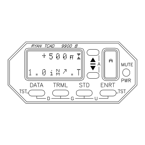
TCAD. A unique reverberating tone is used for the Altitude Alerter. BASIC DISPLAYS There are two basic displays on the Ryan TCAD: When the unit is searching, and When a threat is acquired. - Page 24 Search Configuration ¬ TCAD is searching for a threat. Aircraft altitude. ® Self Test Cursor ¯ Mode indicator (shown indicating Enroute Mode). ° Used to adjust TCAD parameters, barometric pressure (altimeter setting); and to engage or disengage the Altitude Alert. ±...
- Page 25 Threat Acquisition ¬ Range is 2.1 indicated Nautical Miles and approximately 1:30. ( the arrow is on the Model 9900B only). Traffic is 300 feet above, converging in altitude. ® Mode indicator (Terminal Mode). ¯ Used to display secondary threat. Used to display third level threat.
- Page 26 This page intentionally left blank.
-
Page 27: The Air Traffic Shield
TERMINAL, STANDARD & ENROUTE MODES The Ryan TCAD provides three quickly selectable shield volumes, designated as the Enroute (ENRT), Standard (STD) and Terminal (TRML) modes. -
Page 28: Ground Mode
Each shield volume is easily programmable by the pilot (see Appendix 1). Once programmed, the shield volumes are retained in memory for future flights. The Shield limits are found in Specifications, Appendix 4. GROUND MODE When the host aircraft is on the ground, traffic taxiing or parked nearby can transmit replies. -
Page 29: Unrestricted Mode
replaces the Ground Mode symbol. The shield dimensions expand by holding the bottom of the shield at 200 feet above the departure elevation, and the top of the shield climbs as the aircraft climbs. The monitored airspace height expands until the ENRT Mode shield size is reached. Then the symbol in the Mode cell changes to an "E"... -
Page 30: Approach Mode
The annunciator light, if installed, will illuminate when traffic is displayed. When traffic is detected in the ENRT shield, TCAD will generate a tone and automatically return to the Enroute Mode. APPROACH MODE The Approach Mode automatically eliminates tones caused by aircraft on the ground as the TCAD-equipped airplane approaches the runway. -
Page 31: Approach Mode
As the aircraft descends, and the lower limit of the Enroute shield is within 100 feet of the selected field elevation, TCAD automatically enters the Approach Mode, as shown by "Ap" in the Mode cell. As the aircraft continues descent, the shield limits will change from Enroute through Standard until the shield reaches the lateral limits of the TRML mode, and the vertical limits of the STD mode. - Page 32 This page intentionally left blank.
-
Page 33: Threat Acquisition
All other information will continue to be displayed. VISUAL AND NON-VISUAL ACQUISITION (Model 9900 and 9900A) When TCAD detects traffic, and the alert sounds, the pilot should view the TCAD display and determine the vertical... -
Page 34: Imminent Alert
separation and range between the host and threat aircraft. The pilot should then visually scan forward of the aircraft, as the warning time is shortest for head-on traffic. If the displayed data does not suggest urgent action, the pilot should continue to scan, giving priority to the region ahead. If the vertical separation is small, and the range is decreasing, the pilot should take steps to establish the location of the traffic and maintain vertical separation. -
Page 35: Multiple Threats
Generally, the shield size should be reduced when three threats are detected within the monitored area. MODE A IMAGES The Ryan TCAD processing function decodes and pairs Mode A and C replies from threat aircraft, and sends the data on to be prioritized and displayed. -
Page 36: Mute
MUTE The mute button silences audible warnings for a specified duration. When activated, an upper case "M" appears on the display. Mute does not disable Altitude Alert tones. The mute time is pilot adjustable (see Appendix 1). Pressing the mute button when mute is activated will restore the audible alerts. -
Page 37: Update Rate
UPDATE RATE TCAD is updated by transponder replies from threat aircraft. The rate of update is directly related to the density of the Secondary Surveillance radar environment interrogations from TCAS-equipped aircraft. transponder reply light provides an indication of the update rate. - Page 38 This page intentionally left blank.
-
Page 39: Altitude Displays
SECTION V ALTITUDE DISPLAYS ____________________________________ ____________________________________ When the current ATC-supplied altimeter setting is entered into TCAD, the digital altitude display shown is the same as the altitude shown for your aircraft at the ATC facility. In addition, when a threat has been acquired and the DATA button is pressed, the MSL altitude (or flight level) and ATC assigned transponder code of the threat will be displayed. -
Page 40: Host Altitude Display
HOST ALTITUDE DISPLAY The MSL altitude or the flight level of the host aircraft is displayed in the search configuration. Below 18,000 feet, the TCAD barometric correction can be adjusted to the local altimeter setting. At 18,000 feet and above, the altimeter automatically adjusts to 29.92 inches, and the display will show Flight Level instead of altitude in feet. -
Page 41: Altitude Alert
____________________________________ In the Air Traffic Control environment, an unauthorized deviation in assigned altitude can compromise safety. The Ryan TCAD provides a means to alert the pilot prior to arrival at an assigned altitude, or inadvertent changes in cruise altitude. ENGAGING The Altitude Alert function is activated by pressing the buttons simultaneously. - Page 42 When the Altitude Alert is engaged, a small upper case "A" appears on the display. A reversed-image "A" is shown prior to arrival at the target altitude, and a normal "A" is shown when on the target altitude (See Symbols, Section II). When the Altitude Alert is set for a target altitude and engaged, a short tone will announce that the aircraft has arrived within 500 feet of the target altitude.
-
Page 43: Disengaging
DISENGAGING The Altitude Alert function can be disengaged by pressing the s and t buttons simultaneously. The "A" symbol will disappear from the display. The Altitude Alert will automatically disengage if the aircraft changes 1000 feet from a set altitude. EXAMPLE ¬... - Page 44 ¯ Cleared to descend and maintain 7,000 feet. Reset the Altitude Alert by Pressing the buttons twice, once to disengage, and again to activate. The pilot uses button to set the assigned altitude of 7,000 feet. After 8 seconds, Altitude Alert engages (or manually engaged as before).
-
Page 45: Density Altitude
Density Altitude is determined from pressure altitude and temperature. The Ryan TCAD receives pressure altitude from the onboard altitude encoder. By manually entering the outside air temperature (OAT), the TCAD can compute and display the Density Altitude. -
Page 46: Entering Oat
ENTERING OAT By depressing the s or t button while engaged in the Density Altitude function, the Outside Air Temperature (OAT) on the TCAD can be adjusted to reflect the OAT as reported, or as shown on the OAT gauge. The Density Altitude corresponding to the displayed temperature and aircraft altitude is computed and displayed. -
Page 47: Flying With Tcad
Altitude Alert and Density Altitude features, and Built-in Test. There are three examples of operation in this section, one for each model of the 9900 Series. EXAMPLES OF OPERATION, Model 9900B Power has been applied, and TCAD has completed the initialization sequence. - Page 48 Examples of Operation, Model 9900B The shield sizes could be reset (see Appendix 1), but it is not necessary to adjust them before each flight. For this example, the shield sizes are those set at the factory (see Appendix 3). This illustration shows TCAD has automatically entered the Ground Mode, and is operating in the Search Configuration.
- Page 49 Examples of Operation, Model 9900B Before takeoff, check the area visually for traffic and check the TCAD. TCAD is indicating traffic 400 feet above, closing in altitude, 0.8 iNM away, approximately 1:30. The traffic is then visually acquired on a close-in base to final, and lands before your departure.
- Page 50 Examples of Operation, Model 9900B Passing through 2,900 feet, “traffic” sounds. The traffic shows 500 feet above the host aircraft, closing in altitude, 1.0 iNM, at approximately 10:30. The iNM is getting smaller, indicating closure in range. The traffic is visually acquired to the left front, descending.
- Page 51 Examples of Operation, Model 9900B At 3,500 feet, the Altitude Alert sounds indicating the aircraft is nearing 4,000 feet. At 4,000 feet the reversed- image "A" changes to a normal "A". Traffic is acquired 1,000 feet above at 2.5 iNM, approximately 12:00 o’clock.
- Page 52 Examples of Operation, Model 9900B The traffic continues to close in range, and has changed slightly in altitude. The traffic is acquired visually. The traffic continues to approach, and is nearly overhead. The traffic flies directly overhead and passes behind. You are instructed by ATC to turn 45°...
- Page 53 Examples of Operation, Model 9900B Eventually the traffic, which has climbed to 1200 feet above, leaves the monitored area. Cleared out of 4,000 feet for Flight Level 210. Reset the Altitude Alert to FL 210. Passing through 10,000 feet, the alert sounds. TCAD shows traffic 1,400 feet below, closing in altitude at 2.8 iNM, off the left wing.
- Page 54 Examples of Operation, Model 9900B The altitude separation is getting smaller, but the iNM is slowly increasing, and the traffic is still at about 9:00 o’clock. The traffic is flying a nearly parallel course. Pressing the DATA button reveals the target has a Mode A/C transponder, but no squawk has been acquired.
- Page 55 Examples of Operation, Model 9900B DATA shows the traffic as N864UA, likely airline traffic. Later, the Approach Mode is set in anticipation of descent and landing (See Section III). Descending now, TCAD automatically transitions to the Approach Mode (shown by the “Ap” in the lower right). If a high-rate descent is made, the Dynamic Shield would expand to monitor for traffic below the set shield.
- Page 56 Examples of Operation, Model 9900B Pressing the button, corresponding to the secondary threat, shows additional traffic 1,100 feet above and 2.6 iNM, off the right wing. Note the airplane symbol is reversed (see Threat Acquisition, Section IV and Operating Tips, Section IX).
-
Page 57: Examples Of Operation Model 9900A
EXAMPLES OF OPERATION, Model 9900A Power has been applied, and TCAD has completed the initialization sequence. The altimeter setting can be entered if desired. In the illustration above, current altimeter is 30.14" and the field elevation is 1,700 feet MSL. After a few seconds, TCAD will enter a collision alert configuration (Search or Threat Acquisition). - Page 58 Examples of Operation, Model 9900A All tones are muted (hence the "M") and aircraft at and below 100 feet above the host encoded altitude are not displayed (see Section III for more on Ground Mode). An ATC clearance is received, providing initial clearance to 4,000 feet.
- Page 59 Examples of Operation, Model 9900A After climbing more than 200 feet, the "M" disappears, indicating that the alert tones are enabled. The mode symbol changes to "Dp", indicating departure transition, until the aircraft climbs above the programmed base of the Enroute Mode (see Section III).
- Page 60 Examples of Operation, Model 9900A During climb out, the TCAD automatically transitions to Enroute Mode. At 3,500 feet, the Altitude Alert sounds indicating the aircraft is nearing 4,000 feet. At 4,000 feet the reversed-image "A" changes to a normal "A". Traffic is acquired, 1000 feet above, and 2.5 iNM.
- Page 61 Examples of Operation, Model 9900A The traffic is now climbing, and will shortly leave the monitored area. Cleared out of 4,000 feet for Flight Level 210. Reset the Altitude Alert to FL 210. Passing through 10,000 feet, the alert sounds. TCAD shows traffic 1,400 feet below, closing in altitude at 2.8 iNM.
- Page 62 Examples of Operation, Model 9900A The altitude separation is getting smaller, but the iNM is staying about the same. The traffic is probably flying a parallel course. Pressing the DATA button reveals the target has a Mode A/C transponder, but no squawk has been acquired. ATC verifies the traffic climbing to 9000 feet.
- Page 63 Examples of Operation, Model 9900A DATA reveals the traffic as N864UA, likely airline traffic. Later, the Approach Mode is set in anticipation of descent and landing (See Section III). Descending now, TCAD automatically enters the Approach Mode (as shown by the “Ap”). If a high-rate descent is made, the Dynamic Shield would expand to monitor for traffic below the set shield.
- Page 64 Examples of Operation, Model 9900A Pressing the button, the secondary threat, shows 1,100 feet above and 2.6 iNM. Note the airplane symbol is reversed (see Section IV and Section IX). After a few seconds, only the closer of the two threats is displayed. The traffic eventually passes out of the shield.
-
Page 65: Examples Of Operation Model 9900
EXAMPLES OF OPERATION, Model 9900 Power has been applied, and TCAD has completed the initialization sequence. The altimeter setting can be entered if desired. In the illustration above, current altimeter is 30.14" and the field elevation is 1,700 feet MSL. After a few seconds, TCAD will enter a collision alert configuration (Search or Threat Acquisition). - Page 66 Examples of Operation, Model 9900 An ATC clearance is received, providing initial clearance to 4,000 feet. The Altitude Alert can be set for 4,000 feet (see Section VI). When passing through 3,500 feet, a tone will sound as a reminder of arrival at the assigned altitude.
- Page 67 Examples of Operation, Model 9900 After climbing more than 200 feet, the "M" disappears, indicating that the alert tones are enabled. “Dp” indicates departure transition. As the aircraft climbs, TCAD will automatically change to Enroute (see Section III). Note the reversed-image "A"...
- Page 68 Examples of Operation, Model 9900 After the traffic passes, altitude separation and range increase. At 3,500 feet, the Altitude Alert sounds indicating the aircraft is nearing 4,000 feet. At 4,000 feet the reversed- image "A" changes to a normal "A".
- Page 69 Examples of Operation, Model 9900 Pressing the DATA button shows the traffic 5,000 MSL. ATC identifies the traffic at 5000 feet. The traffic is now climbing, and will shortly leave the monitored area. Later in the flight, the alert sounds. TCAD shows traffic 1,400 feet below, closing in altitude at 2.8 iNM.
- Page 70 Examples of Operation, Model 9900 The altitude separation is getting smaller, but the iNM is staying about the same. The traffic is probably flying a parallel course. Later, the Approach Mode is set in anticipation of descent and landing (See Section III).
- Page 71 Examples of Operation, Model 9900 Pressing the button, corresponding to the secondary threat, shows additional traffic 1,100 feet above and 2.6 iNM. Note the airplane symbol is reversed (see Threat Acquisition, Section IV and Operating Tips, Section IX). After a few seconds, only the closer of the two threats is displayed.
- Page 72 This page intentionally left blank...
-
Page 73: Operating Tips
SECTION IX OPERATING TIPS ____________________________________ ____________________________________ SCANNING To optimize use of the data provided by TCAD, the pilot should consider where the greatest potential for collision is, and how to best find the traffic. If the threat aircraft is well above or below your airplane, no action may be necessary on your part to avoid the threat and the traffic can be located if desired. -
Page 74: No Alt" Replies
"NO ALT" REPLIES Many aircraft have encoding altimeters that require warm- up time. The replies received from warming-up encoders do not contain altitude data. TCAD will indicate NO ALT from these aircraft, until their encoder is provides altitude data. These replies often come from aircraft interrogated while on the ground. -
Page 75: Display Priority
The location of the transponder antenna on the threat aircraft can affect TCAD performance. A shadowed signal will reduce the ability of TCAD to detect the traffic. Antenna patterns can also cause an increase in the radiated signals, making the iNM closer than actual distance. These anomalies are more pronounced beyond three iNM. -
Page 76: Dynamic Shield
DYNAMIC SHIELD (Models 9900A and 9900B) If the host aircraft climbs (or descends) more than 800 feet per minute, traffic 500 feet above (or below) the boundary of the selected shield will be displayed. Alert tones will not be issued until the TCAD detects shield penetration. This gives the pilot awareness of traffic beyond the selected shield that may become a threat. -
Page 77: Multiple Threats
MULTIPLE THREATS When a second target is detected within the selected Air Traffic Shield, a small aircraft symbol is shown. Another aircraft symbol is displayed when a third threat is detected. Generally the shield size should be reduced when three threats are detected within the monitored area. -
Page 78: Monitoring Traffic
MONITORING TRAFFIC Even when traffic is visually acquired, it may be difficult to maintain visual contact. Monitor TCAD for unexpected changes in altitude or iNM. SCALLOPING Antenna transmission and reception patterns exhibit a property that can be helpful in traffic awareness. The effect, called scalloping or lobing, is non-uniformity in signal strength around antennas, and can be used as an indication that the traffic could be on a collision course. -
Page 79: Considerations For Setting Shield Radius
CONSIDERATIONS FOR SETTING SHIELD RADIUS Shield radius settings should be optimized (see Setup, Appendix 1). If the shield radius is set too high, extraneous alerts will be sounded from aircraft that are no threat. If set to an excessively small value, warning time is compromised. Use minimum values that provide adequate warning time. -
Page 80: Profile Display
PROFILE DISPLAY By presenting traffic data in profile, emphasizing altitude separation, the complexity of traffic alert is greatly simplified. Any traffic not close in altitude can be disregarded, and multiple threats can be simply recognized and resolved (see Multiple Threats, Section IV). DUAL DISPLAY OPERATION If a second display is installed, common functions such as altimeter setting and mode selection can be made from one... -
Page 81: Built-In Test & Fault Displays
SECTION X BUILT-IN TEST & FAULT DISPLAYS ____________________________________ ____________________________________ A TCAD built-in test function and Performance Monitor is provided. Electronic detection of faults is limited. observant pilot is the best and most effective monitor of the equipment. Initiate the test by pressing the DATA and ENRT buttons simultaneously. - Page 82 This page intentionally left blank.
-
Page 83: Appendix 1 Setup
APPENDIX 1 SETUP ____________________________________ ____________________________________ PROGRAMMING The user can set several parameters in the TCAD. These parameters are kept in memory, and do not have to be adjusted until desired. This allows flexibility for the pilot, yet requires minimum effort before flight. To engage a programming function, the appropriate button is pressed twice. -
Page 84: Tone Options
TONE OPTIONS To select default tone options, depress the Mute button twice. The Tone Volume can be adjusted using the up or down buttons. Depress Mute again to adjust Mute Time Duration. Depressing the Mute button again allows enabling or disabling of voice traffic alerts. A final press of Mute will return the TCAD to collision alert operation. -
Page 85: Appendix 2 Limits
APPENDIX 2 LIMITS ____________________________________ ____________________________________ The TCAD only displays intruders equipped with operative transponders. TCAD provides no indication of traffic conflicts with aircraft without transponders, or where the threat aircraft is outside a Secondary Surveillance Radar (SSR) environment. AIRFRAME SHADOWING Microwave energy can be obstructed by the airframes of both the host and threat aircraft. -
Page 86: Signal Reflections
Traffic information provided by the Ryan TCAD does NOT relieve the pilot in command of this responsibility. -
Page 87: Appendix 3 - Excerpts
APPENDIX 3 EXCERPTS ____________________________________ ____________________________________ Excerpts from AC 90-48C; Pilot's Role in Collision Avoidance. PURPOSE. This advisory circular is issued for the purpose of alerting all pilots to the potential hazards of midair collision and near midair collision, and to emphasize those basic problem areas related to the human causal factors where improvements in pilot education, operating practices,... - Page 88 maintaining a vigilant lookout regard- less of the type of aircraft being flown. Remember that most MAC accidents and reported NMAC incidents occurred during good VFR weather conditions and during the hours of daylight. Visual Scanning. (1) Pilots should remain constantly alert to all traffic movement within their field of vision, as well as periodically scanning the entire visual...
- Page 89 their eyes may require several seconds to refocus when switching views between items in the cockpit and distant objects. Proper scanning requires the constant sharing of attention with other piloting tasks, thus it is easily degraded by such psychophysiological conditions such as fatigue, boredom, illness, anxiety, or preoccupation.
- Page 90 aircraft appears to have no relative motion, it is likely to be on a collision course with you. If the other aircraft shows no lateral or vertical motion, but is increasing in size, take immediate evasive action. (6) Visual search at night depends almost entirely on peripheral vision.
- Page 91 is important that this be accomplished even though a taxi or takeoff clearance has been received. (ii) During climbs and descents in flight conditions which permit visual detection of other traffic, execute gentle banks left and right at a frequency which permits continuous visual scanning of the airspace about them.
- Page 92 related to airspace information depicted on aeronautical charts. (iii) Develop a working knowledge of the various airspace segments, including the vertical and horizontal boundaries. (iv) Develop a working knowledge of the specific flight rules (FAR 91) governing operation of aircraft within the various airspace segments.
- Page 93 military low-level high-speed training routes; instrument approach areas; and areas of high density jet arrival/ departure routings, especially in the vicinity of major terminals and military bases. Use of Communications Equipment and Air Traffic Advisory Services. (1) One of the major factors contributing to the likelihood of NMAC incidents in terminal areas that have an operating air traffic control (ATC)
- Page 94 available to pilots, including information on VFR advisory services, radar traffic information services for VFR pilots, and recommended traffic advisory practices at nontower airports. (B) The airport/facility directory contains a list of all major airports showing the services available to pilots and the applicable communication frequencies.
- Page 95 traffic volume, controller workload, unknown traffic etc., may prevent the controller from providing timely traffic advisory information. Traffic advisories are secondary to the controllers' primary duties (which are separating aircraft under their control and issuing safety advisories when aware of safety conflicts). Therefore, the pilot is responsible for seeing and avoiding other traffic.
- Page 96 (ii) When entering a known traffic pattern at a nontower airport, keep a sharp lookout for other aircraft in the pattern. Enter the pattern in level flight and allow plenty of spacing to avoid overtaking or cutting any aircraft out of the pattern. (iii) When approaching an unfamiliar airport fly over or circle the airport at least 500 feet above...
-
Page 97: Appendix 4 Specifications
500 FT to 1500 FT 1.0 iNM to 3.0 iNM ENRT: 1000 FT to 2000 FT 2.0 iNM to 5.0 iNM (6.0 for Mode S traffic) UNRESTRICTED MODE: ±10,000 FT and 6.0iNM 9900A and 9900B: ±5,000 FT and 3.0iNM Model 9900:... -
Page 98: Factory Settings
FACTORY SETTINGS TCAD is delivered with the following default settings: Audio Volume: Mid Range Mute Duration: 30 seconds Voice: Enabled ±2000 feet, 3.0 iNM ENRT Shield Size: ±1000 feet, 2.0 iNM STD Shield Size: ±500 feet, 1.0 iNM TRML Shield Size: Altimeter Setting: 29.92 inches Density Altitude... -
Page 99: Parts And Service Warranty
No other warranty is expressed or implied. Proper installation of the Ryan TCAD is the responsibility of the installing agency, and is not part of this warranty. Ryan International Corporation is not liable for consequential damages. -
Page 100: Disclaimer
DISCLAIMER The Ryan TCAD has been meticulously designed to provide warning of nearby traffic. As with any device, there are significant limitations. The TCAD can only detect signals if they are received. There are many impediments that prevent the signal from being received, including the lack of interrogation signals, and the relative signal patterns of the transmitting and receiving antennas. -
Page 101: Multifunction Display Interface Supplement
Information regarding specific displays is found at the end of this supplement. Operator Controls & Basic Displays The Ryan TCAD Model 9900B Display serves as the TCAD controller and digital-profile traffic display. The MFD shows traffic information in a plan-view, graphical presentation. - Page 102 The Air Traffic Shield The range and height of the TCAD-monitored area is controlled by the shield size selected on the TCAD. The range selected on the TCAD is the maximum range limit for traffic displayed on the MFD. Thumbnail Display: The solid circle is always one mile.
- Page 103 Threat Acquisition TCAD will respond normally to traffic acquisition, and the MFD will show the traffic as long as the bearing is available for the traffic (see limitations). As with other MFD functions, selecting the smallest TCAD range consistent with operations is best to minimize clutter on the display.
- Page 104 Appendix 1 Limitations TCAD uses transponder replies to track traffic. If the reply rate is low and your aircraft turns, there will be a momentary lag in the position change of the traffic. If your MFD supplies a heading correction, there should be little display lag due to turning your aircraft.
- Page 105 Appendix 3 (Reserved)
- Page 106 Appendix 4 Interface with Ryan TCAD 9900B and the Argus Series Moving Map Displays. There are two ways to access secondary functions on the ARGUS. INFOrmation can be accessed by pressing [ENR] and [AUX], or with a remote switch or button on the panel or the yoke.
- Page 107 Figure 1 Thumbnail Traffic Display...
- Page 108 Figure 2 Full-screen Traffic Display When the INFORmation Mode is selected the TCAD thumbnail view will expand to a full-screen view (see Figure 2). The full- screen view shows the altitude separation next to each threat. When the TCAD is displayed on the full-screen, pressing the SELect button will cause an individual threat to be tagged with a rectangle containing the MSL altitude (or Flight Level) of that threat (this is called the Traffic Selection function).
- Page 109 Figure 3 TCAD/ARGUS Help Screen with TCAD Symbol Information AMEND TCAD is selected in the ARGUS AMEND Mode. There are three choices: ADF/TCAD: MP+PL: This means the ADF and TCAD will be displayed in the thumbnail view on the maps and in the large- screen plan view.
- Page 110 ADF Mode: This means the thumbnail view is not shown, but TCAD information is shown in the large-screen plan view. The selection also affects the display of the ADF (the ADF card is shown full time). The same amend page will also enable the TCAD help page to be displayed.
- Page 111 display. available in all modes except ARRival. See Figure 3 for symbol information. Function Press Result To go from the Press INFO Expanded TCAD thumbnail TCAD information is display to the full- displayed. See Figure screen TCAD display To go from the Hold INFO for The thumbnail display full-screen TCAD...
- Page 112 To go from the Hold INFO button Thumbnail view is help screen back down for more shown to the thumbnail than one second. view Disclaimer The ARGUS display is supplemental to the TCAD display. Traffic information about the traffic, particularly regarding the altitude separation, is available immediately by viewing the TCAD display.
-
Page 113: Index
Index "A" See Altitude Alert "Ap" transition symbol Components 6 Concept 2 AC 90-48C excerpts 75 Considerations for setting Advisory Circular 75 shield height 67 Airframe Shadowing 73 Considerations for setting Air Traffic Shield 15 shield radius 67 Alert Tones 78 Controls, operator 8 Altimeter Setting 27 Customer service number... - Page 114 I - J - K ENRT See Enroute Mode Imminent Alert 22 ENRT symbol 10 Indicated Nautical Miles Encoder accuracy 27 Enroute mode 15 iNM increments 63 Examples of Operation 35 iNM trend 63 Factory Settings 86 Limits, Shield 85 Fault Displays 69 Limits, TCAD 73 Features ii...
- Page 115 No Altitude threats 24, 62 Non-Mode C Traffic See Range Considerations No-Altitude threats 25, 62 N-number 24,64 Range determination 4 Range display increments Range trend 5 Radius of shield See Setup Operating Range See Reflections 74 Shield limits Reply overlap 74 Operating tips 61 Reply signals, use of 2 Operating voltage 85...
- Page 116 Signal reflections 74 Specifications 85 Squawk of threat See DATA Standard Mode 15 Symbols 10 "U" See Unrestricted Mode Unrestricted Mode 17 Update rate 25 TCAD (Traffic and Collision Alert Device) 1 TCAD LIMITS 73 Visual acquisition 21 TRML See Terminal Visual scan 61, 75 Mode Voltage 85...
- Page 117 Copyright 1997, Ryan International Corporation Printed in USA...
Need help?
Do you have a question about the 9900 and is the answer not in the manual?
Questions and answers