Table of Contents
Advertisement
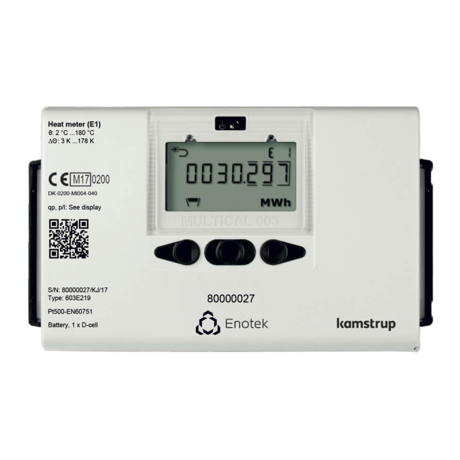
Installation and user's guide
MULTICAL® 603
Heat meter (E1)
θ: 2 °C ...180 °C
∆Θ
: 3 K ...178 K
DK-0200-MI004-040
qp, p/l: See display
S/N: 80000095/K8/17
Type: 603C219
Pt500-EN60751
Battery, 1 x D-cell
B a t t e r y , 1 x D - c e l l
P t 5 0 0 - E N 6 0 7 5 1
T y p e : 6 0 3 C 2 1 9
S / N : 8 0 0 0 0 0 9 5 / K 8 / 1 7
q p , p / l : S e e d i s p l a y
D K - 0 2 0 0 - M I 0 0 4 - 0 4 0
: 3 K . . . 1 7 8 K
∆ Θ
Cooling meter (E3)
θ: 2 °C ...180 °C
∆Θ
: 3 K ...178 K
TS 27.02 012
θhc: See display
θ h c : S e e d i s p l a y
T S 2 7 . 0 2 0 1 2
∆ Θ
: 3 K . . . 1 7 8 K
Advertisement
Table of Contents

Related Manuals for Kamstrup MULTICAL 603


Summary of Contents for Kamstrup MULTICAL 603
- Page 1 Installation and user’s guide MULTICAL® 603 Heat meter (E1) Cooling meter (E3) θ: 2 °C ...180 °C θ: 2 °C ...180 °C ∆Θ : 3 K ...178 K ∆Θ : 3 K ...178 K DK-0200-MI004-040 TS 27.02 012 qp, p/l: See display θhc: See display S/N: 80000095/K8/17 Type: 603C219...
- Page 2 Pt500 - EN 60751, 2-wire connection MULTICAL® 603-D/G - Pt500 Pt500 - EN 60751, 4-wire connection Battery for replacement Kamstrup type HC-993-09 (2 x A-cells) Kamstrup type HC-993-02 (1 x D-cell) Communication Modules An overview of available modules is found in the paragraph Communication modules.
-
Page 3: Table Of Contents
8.10 Wireless M-Bus + pulse outputs, type HC-003-31 8.11 Analog outputs, type HC-003-40 8.12 LON FT-X3 + 2 pulse inputs, type HC-003-60 8.13 BACnet MS/TP + 2 pulse inputs, type HC-003-66 8.14 Modbus + pulse inputs, type HC-003-67 Set-up via front keys Kamstrup A/S • 55122070_A2_GB_07.2017... -
Page 4: General Information
1 General information Please read this guide carefully before installing the energy meter. In case of incorrect mounting, Kamstrup's guarantee obligations no longer apply. By connecting to 230 V supply, there is a risk of electric shock. When working on the flow sensor in the installation, there is a risk of outflow of (hot) water under pressure. -
Page 5: Mounting Of Temperature Sensors
They can also be mounted in installations with standard tee- pieces. Kamstrup A/S can supply R½ and R¾ brass nipples that fit our short direct sensors. The short direct sensor can be also be mounted directly in selected flow sensors from Kamstrup A/S. -
Page 6: Pocket Sensor (Pl)
Push the plastic sleeve on the sensor cable into the sensor pocket and secure the cable by means of the enclosed M4 sealing screw. Fasten the screw with your fingers only. Seal the pockets using seal and locking wire. Kamstrup A/S • 55122070_A2_GB_07.2017... -
Page 7: Mounting Of Flow Sensor
The flow direction is symbolised by an arrow on the flow sensor. 3.1 Mounting of couplings and short direct sensor in flow sensor The short direct sensor from Kamstrup may be 12 mm installed in PN16 installations only. Flow sensor and any mounted blind plug can be used in connection with both PN16 and PN25. -
Page 8: Mounting Of Ultraflow® 54 ≥ Dn150
ULTRAFLOW® must not be mounted with the plastic casing turned to below 0°. It is recommended to turn the plastic casing 45° upwards. 3.3 Mounting of ULTRAFLOW® 54 ≥ DN150 See Installation and user guide no. 5512-887 Kamstrup A/S • 55122070_A2_GB_07.2017... -
Page 9: Flow Sensor Position
MULTICAL® 603 3.4 Flow sensor position Kamstrup flow sensors require neither straight inlet nor straight outlet to meet the Measuring Instruments Directive (MID) 2014/32/EU, OIML R75:2002 and EN 1434:2015. A straight inlet section will only be necessary in case of heavy flow disturbances before the meter. It is recommended to follow the guidelines of CEN CR 13582. -
Page 10: Installations With Two Ultraflow® Sensors
MULTICAL®. Pulse Transmitter ULTRAFLOW® * Electric welding must always be carried out with the earth pole closest to the welding point. Damage to meters due to welding is not comprised by the factory guarantee. Kamstrup A/S • 55122070_A2_GB_07.2017... -
Page 11: Mounting The Calculator
6 mm holes in the wall. Then mount the wall fitting with the enclosed screws and rawlplugs. Mount MULTICAL® on the wall fitting by sliding the calculator onto the fitting in the same way as it is done by compact mounting. Kamstrup A/S • 55122070_A2_GB_07.2017... -
Page 12: Electrical Connection
10 and 30 m to use Cable Extender Box. See further information in the document 5512-2008. 5.4 Electrical connection of Pulse Transmitter If ULTRAFLOW® 54 is used together with third-party equipment, it must be connected through a Pulse Transmitter or Pulse Divider. See instructions 5512-1387 for further information. Kamstrup A/S • 55122070_A2_GB_07.2017... -
Page 13: Connection Of Other Flow Sensors
“Information code”. The battery cannot and must not be charged and must not be short-circuited. Used batteries must be handed in for approved destruction, e.g. at Kamstrup A/S. Further details appear from document on handling and disposal of lithium batteries (5510-408). -
Page 14: Testing Of Function
Carry out an operational check when the energy meter has been fully mounted. Open thermoregulators and valves to enable water flow through the heating system. Activate the front key of MULTICAL® to change display reading, and check that the displayed values for temperatures and water flow are credible values. Kamstrup A/S • 55122070_A2_GB_07.2017... -
Page 15: Information Code
Pulse input A2 Leakage in the system Pulse input A1 Leakage in the system Pulse input A1/A2 External alarm Pulse input B2 Leakage in the system Pulse input B1 Leakage in the system Pulse input B1/B2 External alarm Kamstrup A/S • 55122070_A2_GB_07.2017... -
Page 16: Communication Modules
Note that the pulse figure (litres/pulse) must match the extra water meters and the configurations of inputs A and B. After delivery, the configurations of pulse inputs A and B can be changed by means of the PC program METERTOOL HCW. Kamstrup A/S • 55122070_A2_GB_07.2017... -
Page 17: Pulse Outputs
PC. The signal is passive and galvanically separated by means of optocouplers. Conversion to RS232 level requires connection of data cable 66-99-106 (D-SUB 9F) or 66-99-098 (USB type A) with the following connections: Brown (DAT) White (REQ) Green (GND) Kamstrup A/S • 55122070_A2_GB_07.2017... -
Page 18: M-Bus + Pulse Inputs, Type Hc-003-20
24 and 25 using a twisted pair. The polarity is without importance for the functionality. The meter must be supplied by 24 VAC or 230 VAC. The module requires an external 24 VAC power supply for operating the connected actuator. Kamstrup A/S • 55122070_A2_GB_07.2017... -
Page 19: Wireless M-Bus + Pulse Inputs, Type Hc-003-30
MULTICAL® 603 8.9 Wireless M-Bus + pulse inputs, type HC-003-30* The wireless M-Bus module has been designed to form part of Kamstrup’s hand-held Wireless M-Bus Reader system, which operates within the unlicensed frequency band in the 868 MHz area. The radio module is available with either internal or external antenna. -
Page 20: Lon Ft-X3 + 2 Pulse Inputs, Type Hc-003-60
8.14 Modbus + pulse inputs, type HC-003-67 Modbus RTU slave module. Communication on RS485 with twisted shielded cables via the terminals 137, 138 an 139. The meter must be supplied by 24 VAC or 230 VAC. Kamstrup A/S • 55122070_A2_GB_07.2017... -
Page 21: Set-Up Via Front Keys
** The clock can, under installation seal, be adjusted by all modules. *** q can only be changed on meter type 6. If you attempt to access this menu on the meter types, the display shows the message “Off”. Kamstrup A/S • 55122070_A2_GB_07.2017... - Page 22 MULTICAL® 603 Kamstrup A/S • 55122070_A2_GB_07.2017...
- Page 23 Display readings are based on DDD-code 310 /610. At kamstrup.com, you can find a selection of interactive user guides based on other DDD-codes.
- Page 24 User Guide MULTICAL® 603 Heat meter (E1) Cooling meter (E3) θ: 2 °C ...180 °C θ: 2 °C ...180 °C ∆Θ : 3 K ...178 K ∆Θ : 3 K ...178 K DK-0200-MI004-040 TS 27.02 012 qp, p/l: See display θhc: See display S/N: 80000095/K8/17 Type: 603C219...
Need help?
Do you have a question about the MULTICAL 603 and is the answer not in the manual?
Questions and answers
Does the sensor pocket need to be 10 diameters or 5 diameters away from the heat meter