Table of Contents
Advertisement
Gasoline Fume Detection System
With Blower Control
Single Channel Systems
G-1BB-R (Black, Round, Blower Control)
G-1CB-R (Chrome, Round, Blower Control)
Dual Channel System
G-2BB-R (Black, Square, Blower Control)
Owner's Manual
&
Installation Instructions
Read and comply with all instructions, warnings and limitations before
installing, servicing or removing this device.
1
Part Number 18141, F, 11/06/2017
Advertisement
Table of Contents

Subscribe to Our Youtube Channel
Related Manuals for Xintex G-1BB-R

Summary of Contents for Xintex G-1BB-R
- Page 1 Gasoline Fume Detection System With Blower Control Single Channel Systems G-1BB-R (Black, Round, Blower Control) G-1CB-R (Chrome, Round, Blower Control) Dual Channel System G-2BB-R (Black, Square, Blower Control) Owner’s Manual & Installation Instructions Read and comply with all instructions, warnings and limitations before installing, servicing or removing this device.
-
Page 2: Table Of Contents
Additional copies of this manual are available at no charge by contacting the manufacturer, distributor or dealer. Fireboy-Xintex reserves the right to change features without notice. General Information Specifications Operation of Xintex Gasoline Fume Detector(s) Installation Installing the Display Unit (G1BR-B01-D/G1CR-B01-D or G2BS-B01-D) Routing Sensor Cable(s) (FS-X01 CABLE XX’) -
Page 3: General Information
IS NOT MEANT TO REPLACE STANDARD SAFETY PRACTICES WHICH SHOULD BE CARRIED OUT AROUND EXPLOSIVE GASES. The G-1BB-R, G-1CB-R, and G-2BB-R Gasoline Fume Detectors are an effective means to monitor gasoline fumes in an engine compartments, leaking fuel tanks, or fumes from un-burnt hydrocarbons emitted from faulty exhaust systems. -
Page 4: Operation Of Xintex Gasoline Fume Detector(S)
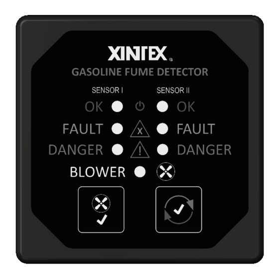
Operation of Xintex Gasoline Fume Detector(s) There are 3 LEDs located on the Display Unit for each channel on the system, as well as an LED for the Blower status. The Green LED, located at the top, indicates that the system is operational. - Page 5 Part Number 18141, F, 11/06/2017...
-
Page 6: Installation
Installation Installing the Display Unit (G1BR-B01-D/G1CR-B01-D or G2BS-B01-D) The Display Unit should be located at the instrument panel, so that the visible and audible indicators may be easily observed. Drill a 2-1/16” hole to accommodate the G1BR-B01-D/G1CR-B01-D Display Unit. Drill a 2-1/8” hole to accommodate the G2BS-B01-D Display Unit. Insert Display Unit into hole and secure with the provided threaded mounting nut. -
Page 7: Electrical Connections (G1Br-B01-D/G1Cr-B01-D Or G2Bs-B01-D)
Electrical Connections (G1BR-B01-D/G1CR-B01-D or G2BS-B01-D) The Display Unit operates on 9-30 VDC. A Red and a Black 16 GA wire are provided for connecting to the power source. Connect the Red wire to Power (+) with an inline 1.0 Amp fuse. Connect the Black wire to Ground (-). A 2A fused Yellow 16 GA wire is provided for connecting the Display Unit to the Bilge Blower system. -
Page 8: Maintenance
No product may be returned for credit or repair without a written “Returned Material Authorization” (RMA) form. Purchaser must call or email Fireboy-Xintex 616-735-9380 or fireboy@fireboy-xintex.com for a RMA. If due to extenuating circumstances a product is to be returned, after approval it must be received in 100% new/resalable condition. Products stored by the buyer for more than 26 weeks may not be returned for any reason. -
Page 9: Year Limited Warranty
Fireboy-Xintex LLC any other liability in connection with the sale of its products; Fireboy-Xintex LLC shall not be liable for the loss of use, revenue, or profit or for any injury, or for any other consequential or incidental damages, buyer is not relying on seller’s judgment regarding his or her particular requirements, and has had an opportunity to inspect the product to his or her satisfaction.
Need help?
Do you have a question about the G-1BB-R and is the answer not in the manual?
Questions and answers