Table of Contents
Advertisement
Quick Links
ABT
DUAL-BEAM
ABT
ABT
ABT DUAL-BEAM
DUAL-BEAM ACTIVE
DUAL-BEAM
DETECTOR
DETECTOR
DETECTOR WITH
DETECTOR
ACTIVE
ACTIVE PHOTOELECTRIC
ACTIVE
WITH
DIGITAL
WITH
WITH DIGITAL
DIGITAL FREQUENCY
DIGITAL
INSTALLATION
INSTALLATION
INSTALLATION
INSTALLATION GUIDE
PHOTOELECTRIC
PHOTOELECTRIC INTRUDER
PHOTOELECTRIC
FREQUENCY
FREQUENCY
FREQUENCY CONVERSION
GUIDE
GUIDE
GUIDE
INTRUDER
INTRUDER
INTRUDER
CONVERSION
CONVERSION
CONVERSION
Advertisement
Table of Contents

Summary of Contents for Abt ABT-40
- Page 1 DUAL-BEAM ACTIVE PHOTOELECTRIC INTRUDER ABT DUAL-BEAM DUAL-BEAM DUAL-BEAM ACTIVE ACTIVE ACTIVE PHOTOELECTRIC PHOTOELECTRIC PHOTOELECTRIC INTRUDER INTRUDER INTRUDER DETECTOR WITH DIGITAL FREQUENCY CONVERSION DETECTOR DETECTOR DETECTOR WITH WITH WITH DIGITAL DIGITAL DIGITAL FREQUENCY FREQUENCY FREQUENCY CONVERSION CONVERSION CONVERSION INSTALLATION INSTALLATION GUIDE...
- Page 2 ABT-30 ABT-30 (Outdoor (Outdoor 30m, 30m, Indoor Indoor 90m) 90m) ABT-30 ABT-30 (Outdoor (Outdoor 40m, 40m, Indoor Indoor 120m) 120m) ABT-40 ABT-40 (Outdoor (Outdoor 40m, 40m, Indoor Indoor 120m) 120m) ABT-40 ABT-40 (Outdoor (Outdoor 60m, 60m, Indoor Indoor 180m) 180m)
- Page 3 Please install according to the below diagram to avoid interference between beams. Adjustable angle: horizontal vertical 10 Direct sunlight, lamplig Horizontal 180 ( 90 50mm ABT-20 0.6m ABT-30 0.7m ABT-40 1.0m ABT-60 1.5m ABT-80 1.8m ABT-100 100m 2.1m 50mm Guarding distance...
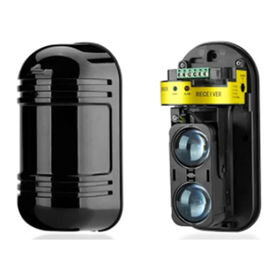
- Page 4 1.Remove the cover Installation Installation of of of of fixed fixed bracket Installation Installation fixed fixed bracket bracket bracket 1.Drill a hole on the bracket and extend out the cable from it. 2.Attach the paper stencil onto the location where the equipment is to be mounted, and drill the holes in the positions on its mark.
- Page 5 1.Remove the cover and connect power. 2.Observe the collimation effect at a distance of 5cm from the viewfinder. 3.Adjust the vertical adjustment screw and the horizontal angle adjusting wheel in order that the image of opposite detector falls into the central part of the viewing hole.
- Page 6 (0.7m/s):4 (0.4m/s):5 (1.2m/s):3 Transmitting The 2 indicators of green LED light up GOOD LEVEL indicators light up The red ALARM indicator light up...
- Page 7 The LED of the transmitter doesn't light up Power open circuit The LED of the receiver doesn't light up Power f open circuit The LED of the receiver doesn't light up when the ABT-20 ABT-30 ABT-40 ABT-60 ABT-80 ABT-100 100m Alert distance 120m 180m 240m...
- Page 8 Recommended installation T-100 120mm T-200 120mm I-100 Installation bracket 100mm I-200 200mm 75mm Dimensions product product approval approval already already The product product has has got got the the 3C 3C and and CE CE approval approval already already and is is is is now now applying applying applying...
Need help?
Do you have a question about the ABT-40 and is the answer not in the manual?
Questions and answers