Advertisement
Quick Links
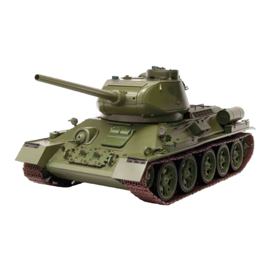
STEP 25
THE T-34-85 IN DETAIL
T-34 tanks produced between 1940-1941 were fitted with a heavy, hinged driver's
hatch which had two bases for prismatic observation devices, or triplexes, in which
a glass prism was fitted in the periscope.
T
he base for the devices was itted in the upper
section of the hatch. Seals itted into grooves welded
to the inside rim, plus plates welded to the external
cover, were supposed to prevent gun shot entering
the tank.
From 1942, a hatch of a simpliied shape with two
prismatic observation devices was introduced, while
the hatch's thickness was increased from 45 to 75 mm.
The cover was locked by means of two latches attached
inner side. A self-locking handle was itted to the central
section of the cover, whose housing was welded
to the inner side.
The cover had two vertical windows for the prismatic
observation devices for the driver. The prisms were
protected on the outside from bullets and shrapnel by two
folding armoured covers that resembled eyelids.
ASSEMBLY GUIDE
The hatch had two
windows for the prismatic
observation devices,
protected from
the outside by hinged
armoured covers
(seen here closed).
1
Advertisement

Summary of Contents for Eaglemoss T-34-85
- Page 1 ASSEMBLY GUIDE STEP 25 THE T-34-85 IN DETAIL T-34 tanks produced between 1940-1941 were fitted with a heavy, hinged driver’s hatch which had two bases for prismatic observation devices, or triplexes, in which a glass prism was fitted in the periscope.
-
Page 2: Component Name
ASSEMBLY GUIDE ASSEMBLY GUIDE CODE CODE COMPONENT NAME QUANTITY COMPONENT NAME QUANTITY 025G NUMBER NUMBER Clip the hinge pins of the two 025A Driver’s hatch 025H Driver’s hatch left lock handle persicope inner covers (025G) 025G 025G 025G 025B Driver’s hatch hinge 025I Driver’s hatch right lock handle firmly into the hinge bases on... - Page 3 T-34-85 more formidable, but the and most importantly, leading the his crew members with installation in it of a powerful new gun. With a 76-mm maximum efectiveness.
- Page 4 ASSEMBLY GUIDE ASSEMBLY GUIDE CODE COMPONENT NAME QUANTITY NUMBER Fit the hull front reinforcement 026B 026A Hull side reinforcement (026B) into the two recessed holes 026B Hull front reinforcement on the front of the upper hull 026C (012A) beside the turret ring base. Fix from 026C Hull U-fork beneath the upper hull with two BP screws.
- Page 5 ASSEMBLY GUIDE STEP 27 THE T-34-85 IN DETAIL The poor quality and location of the T-34’s sight devices was considered a major shortcoming as early as 1940; by 1941 improvements were under way. n 1940, the 360° sight device was installed to the rear and only the PT-4-7 sight could be used for 360°...
- Page 6 ASSEMBLY GUIDE ASSEMBLY GUIDE CODE COMPONENT NAME QUANTITY NUMBER Fit the assembled fuel tank to the 027A External fuel tank 1 upper half two sockets at the rear left of the 027A 027B External fuel tank 1 lower half upper hull (012A), ensuring that the filler cap and handle are at the top.
- Page 7 ASSEMBLY GUIDE STEP 28 THE T-34-85 IN DETAIL Until mid-1943, the quantity and quality of sight devices on the T-34 was poor, which created serious difficulties for all crew members. wo mirrored sight devices were located on the T-34’s – especially in a moving, shaking tank – was virtually front hull plate, while a central mirrored periscope was impossible.
- Page 8 ASSEMBLY GUIDE ASSEMBLY GUIDE CODE COMPONENT NAME QUANTITY NUMBER Fit the peg (028C) through the 028A Hull nose piece loops of both towing hooks (028B). 028B Towing hook Then fit the base of the peg into 028A the socket behind the front left mudguard 028C 028C in the upper hull (012A), ensuring that the...
Need help?
Do you have a question about the T-34-85 and is the answer not in the manual?
Questions and answers