Table of Contents
Advertisement
8879
Users Manual
Cable, Pipe and Fault Locator
RYCOM Instruments
9351 East 59th Street
Raytown, MO 64133
816.353.2100
800.851.7347
Fax: 816.353.5050
www.rycominstruments.com
rycom@rycominstruments.com
now that the world is wired...
where in the world is your wire?
P a r t N u m b e r :
0 3 0 - 0 0 0 8 6 - 0 0
Advertisement
Table of Contents

Subscribe to Our Youtube Channel
Related Manuals for Rycom 8879


Summary of Contents for Rycom 8879
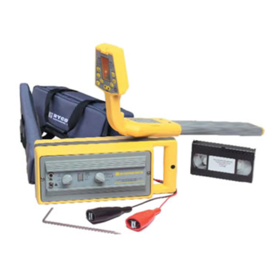
- Page 1 8879 Users Manual Cable, Pipe and Fault Locator RYCOM Instruments 9351 East 59th Street Raytown, MO 64133 816.353.2100 800.851.7347 Fax: 816.353.5050 www.rycominstruments.com rycom@rycominstruments.com now that the world is wired... where in the world is your wire? P a r t N u m b e r :...
-
Page 2: Table Of Contents
Depth Measurement 45º Angle Method ....14 Tilted Magnetic Field Identification ..... . .14 8879 AULT OCATING WITH THE Introduction . -
Page 3: Introduction
EADSET Prepare for Use Unpack your new RYCOM locator. Make sure there is no shipping damage and all the parts are included. Locate the battery compartment on the back of the “head” of the R . Open the compartment using ECEIVER a phillips screwdriver. -
Page 4: Transmitter Operation
8879 Series Transmitter Controls and Indicators OUTPUT OUTPUT OUTPUT CIRCUIT CIRCUIT SIGNAL BREAKER IMPEDANCE CONTROL 8878 815 H z TX O U TP U T 8 kH z LO A D I N G I / O 82 kH z... -
Page 5: Ac Resistance Indications
Note: When the load indicator does not blink in the 815 Hz mode, this indicates the needs to be plugged in. LACK Transmitter Rechargeable Battery Option If the 8879 T has a rechargeable battery, the battery cover will extend past the main T RANSMITTER RANSMITTER housing shell by approximately half an inch. -
Page 6: Direct Connection
Direct Connection DO NOT CONNECT TO LIVE OR CAUTION ENERGIZED POWER CABLES Direct Connection is the most reliable method of signal application. This method is relatively free of inter- ference. The greatest amount of signal strength can be achieved by this method. Both low and high fre- quency may be used. -
Page 7: Inductive Connection
Inductive Connection This method is convenient to use, and services are not interrupted. No test cords or connections are need- ed. The cable or pipe must have good insulation or non-conductive coating, or the operating range will be short. Place the T on the ground, as close as possible to the path of the cable or pipe. -
Page 8: Notes On Selecting The Tracing Signal
Notes on Selecting the Tracing Signal The choice of 815 Hz, 8 kHz or 82 kHz Frequency is dependent on the conditions of the locate. The 815 Hz, 8 kHz and 82 kHz signals each have their advantages. It is recommended to begin by using the 815 Hz signal, and continue as long as you are confident in the results. -
Page 9: Receiver Operation
8879 Receiver Controls and Indicators BUBBLE LEVEL DISPLAYS ABSOLUTE MODE INDICATOR (For 45 Degree Depth) SIGNAL STRENGTH OR DEPTH INDICATES BATTERIES NEED FREQUENCY TO BE REPLACED INDICATOR SELECTS RELATIVE VOLUME SIGNAL STRENGTH BAR- Off, Low, GRAPH Medium, (single bar or High... - Page 10 Hold the SHIFT Key and press the CURRENT key to toggle on and off the back light. 8879 Head Phone Jack The 8879 can be used with headphones. The jack is located on the back of the receiver head and is labeled with earphone insignia.
-
Page 11: Locating The Cable Or Pipe
Locating the Cable or Pipe Make sure the T is connected and in the ON position. Then move approximately 15 feet (4.5 meters) away RANSMITTER from the T along the path. (Move about 25 feet (7.5 meters) for the Inductive search mode.) RANSMITTER Hold the R so that you can see the LCD bargraph and controls easily. -
Page 12: Null Mode Locating
Peak Mode Locating Continued Trace the path by walking away from the T at a moderate pace. Move the R to the left RANSMITTER ECEIVER and right while walking, following the PEAK indications. As you trace the path, the PEAK meter reading may slowly fade as you move away from the T RANSMITTER Press and release the GAIN buttons as needed to compensate for changes in level (higher or lower). -
Page 13: Absolute Signal Strength
The higher of these two readings will show which conductor is car- rying the greatest locating signal. Note: The 8879 is designed to alert the operator of potential current measurement errors. If the display reads ‘Err’ during a current measurement, the R has detected a condition that could produce inaccurate ECEIVER readings. -
Page 14: Gain Change Indication
GAIN up button will center the meter reading to mid-scale. Likewise, if the meter reading is very high, pressing the GAIN down button will center the meter reading to mid-scale. Passive 50/60 Hz Locating The 8879 R is capable of locating power utility frequencies. This MODE is useful for locating under- ECEIVER ground primary and secondary power utilities. -
Page 15: Depth Measurement 45º Angle Method
Depth Measurement 45º Angle Method Move to the location you want to measure depth. Stay at least 15 feet (4.5 meters) away from the . Move the R left to right across the path until the cable is located. Mark the path on the RANSMITTER ECEIVER ground as precisely as possible using the Null Method. -
Page 16: Fault Locating With The 8879
Fault Locating with the 8879 Fault locating determines the position of an insulated break on an underground conductor. In the case of an insulation fault, some of the signal will return to the T attached to the G RANSMITTER ROUND through a break in the insulation. - Page 17 Ground Return Probe Insertion Circuitry between the ground spikes provides a path for current in the soil returning to the G ROUND The current enters one spike of the G and exits the other spike. The GRP should be ROUND ETURN ROBE inserted into the soil with consistent force and depth.
- Page 18 GRP Receiver Meter Response with Distance Notice in the figure below there is a R signal level increase as the G ECEIVER ROUND approaches a fault and it moves away from the T . A good cable will allow the ETURN ROBE RANSMITTER...
-
Page 19: Onde Ocating With The Introduction
ONDE ECEIVER need a S with a frequency of 815 Hz or 8 kHz to use with the 8879 Receiver. ONDE The key to S locating success is practice and patience. Before going out on your first locate, it is a... -
Page 20: Locating The Sonde
ONDE nals can be located. By locating the ghost signals, the user is confirming the accuracy of the locate. Start by following the suspected path of the pipe and use the 8879 R to locate the S . Stop locat-... - Page 21 NULL. Mark this point (B). Next, measure the distance between these ONDE two points. The depth of the pipe is 0.7 times the distance between the two points. The 8879 is specially designed to measure the S depth digitally. To use this feature, the R must...
-
Page 22: Specifications
8879 Specifications Receiver Operating Frequency 82kHz • 8 kHz • 815Hz • 50/60~RF Antenna Mode Null • Peak (vertical coil) (horizontal coil) Audio Indication Variable pitch audio Current Measurement Display indicated relative current simultaneously between any two selected cables for target cable... - Page 23 8879 Specifications Transmitter Operating Frequency 82 kHz • 8 kHz •815 Hz • Both (815Hz/82kHz) Operating Temperature -4°F to 133º (-20ºC to +55ºC) Indicators AC Load Resistance Measurement Low Bat Indicator Low Bat warning modulated on output signal every 20 seconds.
-
Page 24: Factory Service
The RYCOM 8879 were designed for dependable operation with recommended yearly adjustment or calibration. If, however, your 8879 Series is not working properly, first call the factory to receive an RMA number, then return it to the factory for repair. Send it pre- paid to: RYCOM Instruments, Inc.
Need help?
Do you have a question about the 8879 and is the answer not in the manual?
Questions and answers