Advertisement
Quick Links
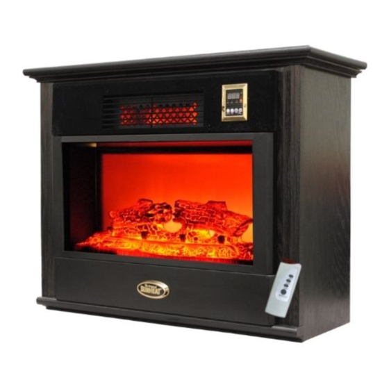
This unit has a grey remote, 1 bottom fan for
the flame effect and 2 top circulation fans
!!Unplug The Heater Before Servicing!!
A. Remove Center From The Wood Mantle
B. Remove Center Top Cap
C. Remove Front Glass
D. Remove Fire Log Set & Firelight Screen
E. Replace Heat Tubes
F. Replace High Limit Switch (120c)
G. Replace Flame Effect On/Off Switch
H. Replace Flame Effect Fuse (1 amp)
F-15 Gen IV Fireplace
Repair Guide
(Remember That The Edges Of The Metal Are Sharp. Use Caution)
Advertisement

Related Manuals for Sunheat F-15 Gen IV

Summary of Contents for Sunheat F-15 Gen IV
- Page 1 F-15 Gen IV Fireplace Repair Guide This unit has a grey remote, 1 bottom fan for the flame effect and 2 top circulation fans !!Unplug The Heater Before Servicing!! (Remember That The Edges Of The Metal Are Sharp. Use Caution) A.
- Page 2 I. Replace Master Reset Breaker (16 amp) J. Replace Heat Exchanger Circulation Fans (12 volt) K. Replace Tip Over Switch L. Replace Power Routing Board M. Replace Circuit Board N. Replace Display Screen O. Replace Air Temperature Sensor P. Replace Flame Effect Light Bulb Socket Q.
- Page 3 Remove Center From The Wood Mantle !!Unplug The Heater Before Servicing!! (Remember That The Edges Of The Metal Are Sharp. Use Caution) Unscrew the 4 wing bolts that hold the fireplace center into the wooden mantle (See Wing Bolt Locations Below). After the removal of the wing bolts, slide the fireplace center out the front of the mantle.
- Page 4 Remove Center Top Cap !!Unplug The Heater Before Servicing!! (Remember That The Edges Of The Metal Are Sharp. Use Caution) With the center removed from the mantle, lower the front grill to gain access to the power switch/fuse/reset button panel. This panel is located on the left side. Remove the 4 screws that hold this panel in place.
- Page 5 Remove the 11 perimeter screws that hold the center top cap in place. Perimeter Screws Perimeter Screws Perimeter Screws...
- Page 6 Lift the top cap upward from the front. NOTE: Be careful not to lift the top cap too far or damage may occur to the wires that connect the display screen to the circuit board. Disconnect the wire harness that runs from the display screen to the circuit board.
- Page 7 Remove Glass !!Unplug The Heater Before Servicing!! (Remember That The Edges Of The Metal Are Sharp. Use Caution) You are able to remove the glass without having to completely dismantle the unit. Loosen the 4 wing bolts that hold the center unit into the wood cabinet and push the center forward slightly.
- Page 8 Remove the 2 metal “U” clips that hold the glass into its channel. The “U” clips are located to the left and right under the metal glass cap. “U” Clip Slide the glass up and out from the guide channel.
- Page 9 Remove Fire Log Set & Fire Light Screen !!Unplug The Heater Before Servicing!! (Remember That The Edges Of The Metal Are Sharp. Use Caution) Remove the 4 screws that hold the fire log set in place. There are 2 screws at each end of the fire log set.
- Page 10 Lift the fire log set up at one end. The log set may be wedged into the case. As you remove, you may have to wiggle slightly to free it. NOTE: The log set is made out of fiberglass. Applying excessive force may cause damage.
- Page 11 Remove the 6 screws that hold the fire light screen into the fireplace. (See Screw Locations Below) Screws Removing the fire light screen will give access to the fire light drive rod, drive rod motor and the AC case fan (bottom flame effect fan). AC Case Fan Drive Rod Drive Rod Motor...
- Page 12 Remove Heat Tubes !!Unplug The Heater Before Servicing!! (Remember That The Edges Of The Metal Are Sharp. Use Caution) You are able to inspect the elements to see which one needs to be replaced. After determining which of the 3 heat tubes has failed, use a 7mm wrench to loosen the nuts on each end of the heat tube that holds the power wires in place.
- Page 13 After removing the heat tube access plate, slide the malfunctioning heat tube out of the heat exchanger. Make sure the nut that secures the wire to the element is tightened securely.
- Page 14 Replace High Limit Switch (120c) !!Unplug The Heater Before Servicing!! (Remember That The Edges Of The Metal Are Sharp. Use Caution) To gain full access to the high limit switch, the heat exchanger assembly needs to be removed. Remove the 4 anchor screws that hold the heat exchanger assembly in place. (See Screw Locations Below) Anchor Screws Anchor Screws...
- Page 15 Once the heat exchange box is free, flip it over so that the black mounting plate is facing up. Remove the 2 bolts from the fan that is closest to the high limit switch. Mounting Plate High Limit Switch After removing the 2 bolts, flip the exchanger box over so the black mounting plate is lying on the bottom.
- Page 16 Using needle nose pliers, hold the nut that holds the high limit switch in place from the inside of the heat exchanger. Use a screwdriver on the other side to remove the screw. After removing the screw & nut, remove the 2 screws that hold the Mica insulator plate in place (See Screws Locations Below).
- Page 17 Replace Flame Effect On/Off Switch !!Unplug The Heater Before Servicing!! (Remember That The Edges Of The Metal Are Sharp. Use Caution) Remove the 4 screws that hold the power switch/fuse/reset button panel in place. NOTE: Mark all of the wires so you know the order to reattach to the new switch. After removing the wires that connect to the switch, use pliers to compress the tabs that lock the switch into the metal plate (See Below).
- Page 18 After compressing the locking tabs on the switch, remove the switch through the front of the plate (See Below). NOTE: Be sure to hook the wires back in the correct order. Failing to do so will result in Switch damage.
- Page 19 Replace Flame Effect Fuse (1 amp) !!Unplug The Heater Before Servicing!! (Remember That The Edges Of The Metal Are Sharp. Use Caution) Place a small flat screwdriver under lifting tab. Carefully lift up fuse holder to gain access to the 1 amp fuse.
- Page 20 Replace Master Reset Breaker (16 amps) !!Unplug The Heater Before Servicing!! (Remember That The Edges Of The Metal Are Sharp. Use Caution) Remove the 4 screws that hold the power switch/fuse/reset button panel in place. Mark the wires so that you know which way they reattach. Hold the master reset breaker from the back as you loosen the threaded securing nut from the front (See Below).
- Page 21 Replace Circulation Fans (Top Fans) !!Unplug The Heater Before Servicing!! (Remember That The Edges Of The Metal Are Sharp. Use Caution) To gain access to the circulation fans, the heat exchanger box must be removed from the fireplace. Remove the 4 anchor screws that hold the heat exchanger box in place. (See Screw Locations Below) Anchor Screws Anchor Screws...
- Page 22 Once the heater exchange box is separated from the fireplace, flip it over so that the black mounting plate is facing up. Remove the 4 bolts from the defective fan. Mounting Plate After removing the 4 bolts, flip the exchanger box back over so the black mounting plate is lying on the bottom.
- Page 23 Replace Tip Over Switch !!Unplug The Heater Before Servicing!! (Remember That The Edges Of The Metal Are Sharp. Use Caution) The Tip Over Switch is located to the right of the Heat Exchanger Box. Remove the wires from the tip over switch. NOTE: Mark the wires so you are able to reattach to the correct location.
- Page 24 Replace Power Routing Board !!Unplug The Heater Before Servicing!! (Remember That The Edges Of The Metal Are Sharp. Use Caution) The Power Routing Board is located to the right of the Heat Exchanger Box and to the rear of the main circuit board (rectangle in shape). Remove the Fan Power plugs and the main Power Supply to the board (See Locations Below).
- Page 25 Replace Circuit Board !!Unplug The Heater Before Servicing!! (Remember That The Edges Of The Metal Are Sharp. Use Caution) The Circuit Board is located to the right of the Heat Exchanger Box and square in shape. Remove the Circuit Board by removing the 4 screws that hold it in place. These screws are located on all four corners of the board.
- Page 26 Replace Display Screen !!Unplug The Heater Before Servicing!! (Remember That The Edges Of The Metal Are Sharp. Use Caution) Remove the 4 screws holding the access panel in place and unplug Display Screen from the Circuit Board. Remove the 4 screws that hold the function display screen into place on the front cover. Remove the display screen through the front of the cover.
- Page 27 Replace Air Temperature Sensor !!Unplug The Heater Before Servicing!! (Remember That The Edges Of The Metal Are Sharp. Use Caution) The air temperature sensor is located on the bottom right hand side of the fireplace. Unplug from the circuit board and pull the wire through the guide channel. Replace with new temperature sensor and make sure it is plugged in to circuit board.
- Page 28 Replace Flame Effect Light Bulb Socket !!Unplug The Heater Before Servicing!! (Remember That The Edges Of The Metal Are Sharp. Use Caution) There are 2 light sockets located behind the lower access panel. Follow steps: (A), (B), (C) & to remove the glass, log set and firelight screen to gain full access to trace the wires. Hold the base of the light socket with one hand while unscrewing the anchor ring with the other.
- Page 29 Replace AC Case Fan (Bottom Fan) !!Unplug The Heater Before Servicing!! (Remember That The Edges Of The Metal Are Sharp. Use Caution) To gain access to the AC Case Fan follow steps (A), (B), (C) & (D). After gaining clear access to the AC Case Fan, hold each one of the 4 lock nuts in place with a 7mm wrench.
- Page 30 Replace Fire Light Drive Rod Motor Follow steps: (A), (B), (C) & (D) in order to remove the glass, log set and firelight screen and gain access to the drive rod motor. After gaining clear access, manually rotate the drive rod counterclockwise to see the cotter key that holds the drive rod collar onto the drive rod motor.
- Page 31 After removal of the nuts & screws that hold the drive rod motor bracket in place, rotate the drive rod motor assembly to gain access to the wiring. Clip the wire tie that holds the wires Note: together. Take care not to clip the wires Once access to the drive rod motor &...
- Page 32 Replace Power Cord !!Unplug The Heater Before Servicing!! (Remember That The Edges Of The Metal Are Sharp. Use Caution) To gain access to the power cord, follow steps: and (B). Remove the 2 black power leads. One wire is attached to “ACN” terminal on circuit board. The other is attached to the “ACL” terminal on circuit.
- Page 33 Once the glass and screen are removed, use a 7mm wrench to hold the lock nut securing the ground wire in place from the underside of the metal case. Use a 3mm Allen wrench to loosen the screw that runs through the ground wire & metal panel. Lock Nut Ground Wire Screw After disconnecting the power leads and removing the ground wire, turn the fireplace around...
- Page 34 Replace Center Mounting Anchors !!Unplug The Heater Before Servicing!! (Remember That The Edges Of The Metal Are Sharp. Use Caution) To gain clear access to the 4 center mounting anchors, follow steps (A), (B), (C) & (D). Using two sets of pliers, hold the mounting anchor from the inside of the fireplace metal case. Loosen the mounting anchor from the back side of the fireplace case (See Below).
-
Page 35: Wiring Diagram
WIRING DIAGRAM... - Page 36 WIRING DIAGRAM...
Need help?
Do you have a question about the F-15 Gen IV and is the answer not in the manual?
Questions and answers