Table of Contents
Advertisement
Quick Links
Kurz Instruments Inc.
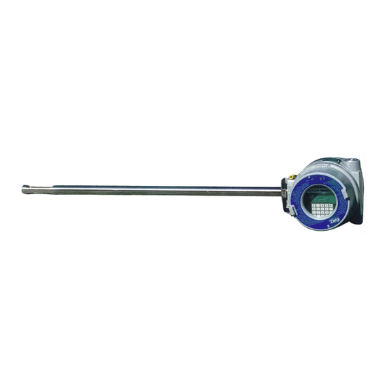
Insertion Mass Flow Transmitter
Covers MFT V 1.2x Firmware
ISO-9001
Series 454FT User's Guide
Kurz Instruments, Inc.
Series 454FT
User's Guide
DCN: 360197-1.2 Rev. A
October 15, 2003
Kurz Instruments Inc.
2411 GARDEN RD
MONTEREY CA 93940-5394
Telephone: (831) 646-5911 or 800-424-7356
FAX: (831)-646-8901 or (831)-646-1033
www.kurz-instruments.com
USA
i
DCN: 360197-1.2 Rev. A
Advertisement
Table of Contents

Summary of Contents for Kurz Instruments, Inc 454FT-08-MT
- Page 1 Kurz Instruments Inc. Kurz Instruments, Inc. Series 454FT Insertion Mass Flow Transmitter User’s Guide DCN: 360197-1.2 Rev. A Covers MFT V 1.2x Firmware October 15, 2003 ISO-9001 Kurz Instruments Inc. 2411 GARDEN RD MONTEREY CA 93940-5394 Telephone: (831) 646-5911 or 800-424-7356 FAX: (831)-646-8901 or (831)-646-1033 www.kurz-instruments.com...
-
Page 2: Publication Notices
In addition, Kurz Instruments, Inc. makes no representations or warranties of any kind concerning the contents of this publication. Under no circumstances will Kurz Instruments, Inc. be held liable for any loss or other damages pertaining to the use of this publication. - Page 3 Kurz Instruments Inc. Equipment sold by Kurz Instruments, Inc. is not intended for use in connection with any nuclear facility or activity unless specifically sold for such applications and specific conditions for such usage are detailed. If the equipment is used in a nuclear facility or activity without supporting quotation, Kurz Instruments, Inc.
- Page 4 The Leader in Mass Flow Flow Technology for Process and Environmental Measurements Kurz Instruments, Inc. • 2411 Garden Road, Monterey, CA93940 • 800-424-7356 • 831-646-5911 • FAX 831-646-8901 email: sales@kurz-instruments.com • www.kurz-instruments.com...
-
Page 5: Table Of Contents
Kurz Instruments Inc. Table of Contents Title Page......................i Publication Notices....................ii-iii Copyright..................... ii Trademarks....................ii Publication Notice..................ii-iii Standard Terms and Conditions of Sale ............iv Table of Contents....................v-xi Introduction......................1-2 Duct Velocity Profile Correction..............1 Sensor Insertion Location................1 Duct Area.................... - Page 6 Kurz Instruments Inc. Mounting...................... 7 Figure 1 Model 454FT Installation with Compression Fitting...... 8 TS Version..................9 Field Wiring....................9 Safety....................9 Typical Hook-Up Wiring Diagrams..........10 24 VDC Powered Flow Transmitters..........10 AC Powered Units................11 Analog Output................... 11-12 Alarms....................
- Page 7 Kurz Instruments Inc. Selecting Menus..................19 Entering Data..................... 19 Clearing Data, Editing Data or Exiting Menus..........19 Holding a Menu For Display............... Help Display....................20 Flow Meter Time Constant................20 Data Logging....................20-21 Configuration Data Storage................. 21-24 Figure 3. Series MFT Memory Configuration........22 Configuration, Upload/Download............23 Calibration of the Analog Output..............
- Page 8 Kurz Instruments Inc. Flow Meter Correction Factors..............30-32 Variable Correction Factor (VCF) Setup..........30-31 Sensor Blockage Correction Factor (SBCF) Setup......31-32 Low & High Kick-Out..................32 Low Flow Cut-Off..................32 Scroll Meter....................33-34 Meter Filter....................34 Analog Output Range................. 34 Analog Output Calibration................36-37 Totalizer Reset....................
- Page 9 Kurz Instruments Inc. Field Calibrations..................48 Sensor Velocity Calibration................. 48 Factory Calibrations................49 User Calibrations................49 Figure 5 Typical Calibration Sheet (DCN 180117)......52 Figure 6 Typical Calibration Curve........... 53 Maintenance and Troubleshooting..............54-62 Maintenance....................54 Flow Issues....................55 Sensor......................
- Page 10 Kurz Instruments Inc. Reynolds Number................A1-A2 Standard Velocity................A2 Standard Volumetric Flow..............A3 Mass Flow..................A3-A4 Gas Property Induced Errors............... A4-A5 Pressure Changes................A4 Temperature Changes..............A4 Temperature Profiles..............A4 Low Flow Free Convective Forces..........A4 Wet vs. Dry Flow Rate..............A4-A5 Flow Profiles....................
- Page 11 Kurz Instruments Inc. Appendix B Product Approvals................B1-B2 Series MFT ATEX Declaration of Compliance (DCN 430040)..................... B2 Appendix C MFTCOMM..................C1-C7 Installation....................C2 Menus......................C2-C3 Setup for Upload/Download................ C3 Saving an MFT configuration on your PC........... C3-C4 Viewing or Printing the Configuration File........... C4 Downloading a Configuration from the PC to the MFT Unit......
-
Page 12: Introduction
Kurz Instruments Inc. Introduction The Kurz Instruments 454FT series of insertion mass flow transmitters are point velocity sensing devices. This bivariable transmitter also measures the process temperature. The flow element is a constant temperature thermal anemometer which intrinsically measures the process fluid Reynold’s number. The net meter response is mass rate per unit area. -
Page 13: Flow & Temperature Output Range
Kurz Instruments Inc. - Sensor blockage, reducing the effective area. Flow & Temperature Output Range: - What scale do you want the 4-20 mA output set to? Field Calibration: - From a field calibration, either velocity dependent correction factors or a simple gain correction can be entered to account for the duct flow profile. - Page 14 S E R I E S 454FT INSERTION MASS FLOW TRANSMITTERS 9001 ™ INSTRUMENTS INC.
- Page 15 Remote Electronics Enclosure option. ¤ improve their business. Velocity range of 0-18,000 SFPM. ¤ Kurz Instruments, Inc. 2411 Garden Road, Monterey, CA 93940 Tel 800-424-7356 Fax 831-646-8901 www.kurz-instruments.com e-mail: sales@kurz-instruments.com PAGE 2...
-
Page 16: Principle Of Operation
Versus Rotation/Yaw Angles. FLOW 2000 4000 6000 8000 10,000 12,000 VELOCITY (SFPM) FLOW Figure 3–Calibration Curve. – ROTATION Figure 7–Sensor Rotation and Yaw Description. Kurz Instruments, Inc. 2411 Garden Road, Monterey, CA 93940 Tel 800-424-7356 Fax 831-646-8901 www.kurz-instruments.com e-mail: sales@kurz-instruments.com PAGE 3... - Page 17 Kurz Model 400D NIST traceable wind tunnel. Kurz Instruments, Inc. 2411 Garden Road, Monterey, CA 93940 Tel 800-424-7356 Fax 831-646-8901 www.kurz-instruments.com e-mail: sales@kurz-instruments.com PAGE 4...
- Page 18 LCD/Keypad, power supply, and all of the other features of the Series 155 Mass Flow Computer. (Please see the Series 155 brochure). Kurz Instruments, Inc. 2411 Garden Road, Monterey, CA 93940 Tel 800-424-7356 Fax 831-646-8901 www.kurz-instruments.com e-mail: sales@kurz-instruments.com PAGE 5...
-
Page 19: Ordering Information
Description Option Description Optional Flange U Dimension 115 VAC, 50/60 Hz +24 VDC Electronics Enclosure Configuration/Input Power 230 VAC, 50/60 Hz Special Kurz Instruments, Inc. 2411 Garden Road, Monterey, CA 93940 Tel 800-424-7356 Fax 831-646-8901 www.kurz-instruments.com e-mail: sales@kurz-instruments.com PAGE 6... - Page 20 Contact the Kurz Representative or the Kurz Factory to place the order Temperature Range,Air and N only. or to obtain additional information. Kurz Instruments, Inc. 2411 Garden Road, Monterey, CA 93940 Tel 800-424-7356 Fax 831-646-8901 www.kurz-instruments.com e-mail: sales@kurz-instruments.com PAGE 7...
- Page 21 ⁄ " [12.7mm] 24 VDC 3.50" [88.9mm] 2.82" [71.6mm] 454FT-12 ⁄ " [19.1mm] 24 VDC 2.82" [71.6mm] 2.82" [71.6mm] 454FT-16 1" [2.54mm] Kurz Instruments, Inc. 2411 Garden Road, Monterey, CA 93940 Tel 800-424-7356 Fax 831-646-8901 www.kurz-instruments.com e-mail: sales@kurz-instruments.com PAGE 8...
- Page 22 Refer to Part No. 759030. IDENTIFICATION TAGS Part Number 170098, 1.25" x 3", 316 SS, maximum of 4 lines, 32 characters per line. Kurz Instruments, Inc. 2411 Garden Road, Monterey, CA 93940 Tel 800-424-7356 Fax 831-646-8901 www.kurz-instruments.com e-mail: sales@kurz-instruments.com PAGE 9...
- Page 23 Technology for Process and Environmental Measurements ™ INSTRUMENTS INC. Kurz Instruments, Inc. 2411 Garden Road, Monterey, CA 93940 800-424-7356 831-646-5911 Fax 831-646-8901 www.kurz-instruments.com e-mail: sales@kurz-instruments.com IMPORTANT NOTICE: Specifications are subject to change without notice. © 1999 Kurz Instruments, Inc. DCN 367047 REV. C...
-
Page 24: Quick Setup Guide
Kurz Instruments Inc. Quick Setup Guide The following is a listing with references for the essential issues needed for installation. See the DCN 360206 pamphlet for more on getting started. Product Approval Requirements Explosive Atmospheres To maintain safety ratings, the unit must have conduit or cable gland seals directly attached to the enclosures. -
Page 25: Output Setup
Kurz Instruments Inc. Output Setup You should first read the basic programming menu navigation section starting on pages 18 & 27 and more on page 36. This will reduce your time spent setting or correcting the configuration of your Series MFT unit. Standard reference conditions are described on page 42. -
Page 26: Installation
Kurz Instruments Inc. Installation WARNING: Your warranty will be void if your unit is not installed in accordance with this user’s guide. Make sure you read and thoroughly understand the installation portion of this guide before you attempt to install your unit. If you have any questions, contact your Kurz customer service representative before attempting installation. -
Page 28: Ts Version
Kurz Instruments Inc. TS Version For transmitter separate versions (TS) there are two enclosure groups. The sensor enclosure mounts as described above and contains just a sensor wire terminal board. The electronics enclosure group contains the bridge electronics, CPU, local display and keypad in the larger enclosure and is mounted via the pipe nipple between it and the sensor wire terminal board enclosure. -
Page 29: Typical Hook-Up Wiring Diagrams
Kurz Instruments Inc. For hazardous areas it is important to not connect or disconnect any wiring when the circuits are energized, the resulting spark could cause ignition. This warning is shown on the safety label of the unit and is very important. Two 3/4"... -
Page 30: Ac Powered Units
Kurz Instruments Inc. (metal oxide varistors) to clamp voltage spikes going into the unit. These are 48 V nominal (voltage level at 1 mA) and do not conduct significant current below about +/- 36 VDC relative to ground. Consequently, the isolated 4-20 mA signals, alarms etc., can not have a significant common mode or bias voltage to prevent leakage currents on the MOVs, which can cause an error in the flow measurement if occurring on the 4-20 mA signal. -
Page 31: Alarms
Kurz Instruments Inc. operation is clipped between 3.8 and 20.5 mA. Sensor kickouts low and high will cause less than 3.6 mA or more than 21 mA respectively. Alarms The two optically coupled solid state relays (SSR), may be used for just about any flow logic you can think of, sensor error output, or totalizer mode pulses. -
Page 32: 5-Wire Sensor Connections
Kurz Instruments Inc. interface. Jumper W3 selects RS-232 or RS-485 for the digital communications. RS-485 This mode is jumper selected at W3 on the I/O board. You may operate full or half duplex using jumpers W1/W2. The remote terminal mode can operate on the RS-485 instead of RS-232 for long distance operation. -
Page 33: Orientation Of The Lcd Keypad
Kurz Instruments Inc. up to 6 feet in length and have compression adaptors to NPT fittings. Thread adapters or bushings may be required for the Kurz enclosures which are 3/4" FNPT. Not recommend for CE compliance on the 5-wire sensor connections of the TS configuration: Type Reason not to use it. - Page 34 Kurz Instruments Inc. PCB connector at each end. The ribbon cable will route towards the center of each PCB when properly mounted. There is an LCD contrast pot on the back of the LCD/keypad board which can be adjusted with a small flathead screwdriver as needed for best viewing of the screen. Series 454FT User’s Guide DCN: 360197-1.2 Rev.
-
Page 35: Operation
Kurz Instruments Inc. Operation This section of the manual describes the basic operation of the unit. Configuration of the parameters such as duct area, analog output range, correction factors, meter identification or tags, etc. are covered in the next section. The signal flow diagram which shows the relationship between the various parts of the Kurz Series MFT display parameters is shown in Appendix. -
Page 36: Overview Of The User Interface
Kurz Instruments Inc. transmitter are available via the keypad and 2x16 LCD. This section of the manual presents the material to configure the Kurz Series MFT units. Overview of the User Interface After boot up or power on, the unit will scroll the display showing some of the principal keys to launch operation. -
Page 37: Selecting Menus
Kurz Instruments Inc. category within program or display mode you can only advance the screens with the key depending on the mode you are in. The v keys within the menu categories are used to change entries or selections. Selecting Menus You select a menu category of interest by pressing the key or Enter on the remote terminal. -
Page 38: Help Display
Kurz Instruments Inc. You may freeze or hold any menu beyond the two minute auto-return interval to view the information like flow rate or temperature by simply pressing the key. This mode is removed by pressing the key. Help Display A list of local commands can be found by pressing the key twice or The help... -
Page 39: Configuration Data Storage
Kurz Instruments Inc. Reply: 13:58 2/09/1999 #1 FT456 0.23459 SCFM 1.238999e3 SCF #2 TT456 125.71 DEGF Format: Time & Date: "Time:" hh:mm mm/dd/yyyy Meter data: Number, Rate, Rate units, Totalization, Tot. units Second meter data (typically temperature with no totalization) The “l”... -
Page 41: Configuration, Upload/Download
Kurz Instruments Inc. To access the EEPROM memory, you must enter to the program mode and select the menu item “PRESS E TO LOAD DATA FROM EEPROM”. The menu will ask you if you want to reload the data from the EEPROMs to the CPU copy. -
Page 42: Calibration Of The Analog Output
Kurz Instruments Inc. floppy disk containing the Factory configuration of your unit. Calibration of the Analog Output Operates similarly to the Series 155 Mass Flow Computer. You enter the menu and must use an external meter to “dial in” the 4.0 mA Zero and then the 20.0 mA Span. keys are used to raise or lower the output until it matches the two conditions listed. - Page 43 Kurz Instruments Inc. Figure 4. NE-43 Alarm signaling on the 4-20 mA outputs. Series 454FT User’s Guide DCN: 360197-1.2 Rev. A...
-
Page 44: Configuration Changes
Kurz Instruments Inc. Configuration Changes After reading over the basic navigation information in the operation chapter, looking over the Signal Flow diagram in Appendix F and Menu-State diagram DCN 342027-1.2 in Appendix E, you can setup or configure anything you need for your Series MFT unit. This section provides detailed step-by-step setup instructions with explanations of what the various parameters are for. -
Page 45: How To Set The Meter Id
Kurz Instruments Inc. PRESS P TO SEE NEXT CHOICE OR This is the one of many menu categories within the program mode. You navigate to the menu category of interest using the key to advance to the next or you can use the keys to move forward and backwards. -
Page 46: Meter Id With A Remote Terminal
Kurz Instruments Inc. or twice depending on how you entered your last character to accept the new ID. Finally you press twice to clear back up to the executive state. Meter ID with a Remote Terminal If you are using a remote terminal, this process is a lot easier because you place the keyboard in Caps Lock and start typing your meter ID using all the numbers, letters and punctuation directly. -
Page 47: Flow Meter Correction Factors
Kurz Instruments Inc. You type the value you want with decimal point then press the local key or enter to accept the new value. Flow Meter Correction Factors There are three available correction factors. They are: Variable Correction Factor (VCF) which is rate dependent. Bias Correction Factor (BCF) which is a constant. - Page 48 Kurz Instruments Inc. press to advance the menu. R1=XXX.XXX FUNIT This is the reference rate, velocity or flow. Press to accept the changes or press advance. The “FUNIT” is the calibration flow unit, it can be one of the following: SFPM, SCFM, SMPS or SCMH.
-
Page 49: Low & High Kick-Out
Kurz Instruments Inc. Press to advance the next screen. SBCF IS X.XXX This is a status screen showing the SBCF computed from the sensor type, sensor support depth and area of the duct or pipe. Press to advance the menu. Low and High Kick-Out Sensor kick-out is a fault condition you can set to remove a sensor whose flow reading or temperature reading is out of bounds. -
Page 50: Low Flow Cut-Off
Kurz Instruments Inc. The low flow cut-off is used to force the flow meter to read zero when the flow rate goes lower than the low flow cut-off point. To setup the low flow cut-off, you enter these screens from: Program mode, Meter #1 Flow, press then press until you reach the following low-flow cut-off screens:... -
Page 51: Meter Filter
Kurz Instruments Inc. SCROLL UPDATE X SEC This menu selects the time a scroll screen menu is held before it is updated. The hold time can be selected using the key and the available choices are 2, 4, 6 or 8 seconds. Meter Filter Each meter has its own first order or RC type low pass filter. - Page 52 Kurz Instruments Inc. All flow calculations internal to the Series MFT use floating point numbers. To connect this large dynamic range to the 4-20 mA analog output (12 bit resolution) we have to specify the low and high scale values. You can assign either or both analog outputs to either or both meters.
-
Page 53: Analog Output Calibration
Kurz Instruments Inc. This screen is where you set the engineering unit (UNIT) value which will correspond to the low output limit of the 4-20 mA channel. Key in your value or use the keys then press to accept the value. HI=XXXXX.X UNIT AT 20.000 mA Now you enter the engineering value you want for the span or 20 mA output current. -
Page 54: Totalizer Reset
Kurz Instruments Inc. accept the value or to skip this screen. The Factory calibration will be so close to what you need that not much change will be required. SET 20.000 mA TO OUT 1 UP=^ DN=v This screen works the same as the 4.000 mA screen but at the 20.000 mA value. After you have calibrated Output #1 you will see the screens prompt you for Output #2. -
Page 55: Log Interval
Kurz Instruments Inc. get to Time & Date category from: Program mode then press the key until you reach the following: PRESS E TO SET TIME & DATE You press the key to enter the time and date menu. HH:MM MM/DD/YYYY This screen is where you enter the hour in 24 hour format. -
Page 56: System Units
Kurz Instruments Inc. screen by typing the value from the keypad or use the keys followed by the key to accept the change. NEW LOG HHH:MM INTERVAL : MM This screen is to set the minutes of the log interval just like the hours. System Units The Series MFT flow meters can show data in English or International units. - Page 57 Kurz Instruments Inc. Totalizer Pulse Output (see Set Pulse Output) Once assigned, the alarm can be On/Off, Normally Open or Closed, Hi, Low, Hi/Low and the set point for the above. You reach the Alarms category from: Program mode, then press the key until you reach the following: PRESS E TO SET...
-
Page 58: Pulse Mode Totalizer Output
Kurz Instruments Inc. in that the rate output goes to zero for the kick-out (meter response is assumed not valid). You select the option of interest with the keys then to accept the new entry. ALARM IS HOL NEXT TYPE ^v This screen is used to select the alarm types other than Kick-out. -
Page 59: Sensor Flow Calibration Data
Kurz Instruments Inc. In this screen you enter 1 or 2 for the pulse output to be configured using the keypad or keys followed by to accept the changes. PULSE OUTPUT #1 ENTER METER #1 In this screen you select which meter goes with the previously selected pulse output. You choose 1 or 2 with the keypad or use the keys then press to accept the... - Page 60 Kurz Instruments Inc. This is a display of the standard reference conditions when it was calibrated from the factory, press the key to advance to the next screen. GAS NAME IS DRY AIR This is the name of the gas that was calibrated and the flow calibration data is referenced.
- Page 61 Kurz Instruments Inc. The following screens control the sensor’s calibration data. If you are not very familiar with this process, do not change any of these settings. Most user changes to a flow meter’s calibration should be done using the Meter Correction Factors. (See pages 28 to 30) NEXT TYPE FLOW UNITS ^v SFPM...
- Page 62 Kurz Instruments Inc. to advance to the next screen without change. PT T1-1=0.180 A This screen is used to enter the sensor’s response for data point 1 of temperature set 1 (T1-1) in Ampere (A). You enter the new value from the keypad followed by the to accept the changes.
-
Page 63: Adc Sample Rate
Kurz Instruments Inc. and 60 Hz options have the property that if you have power frequency noise which is the same as the sample rate it is 100 % rejected. These power frequency rates support the16 bit input resolution. The 250 Hz mode is for fast measurements but at only 13 bit resolution making it noisier. - Page 64 Kurz Instruments Inc. is necessary, the original sensor data from the EEPROM can be loaded to the SRAM. You reach the Load Data from EEPROM category from: Program mode, then press the key until you reach the following: PRESS E TO LOAD DATA FROM EEPROM You press to enter the load data from EEPROM screens.
-
Page 65: Insertion Flow Transmitter Calibration
Kurz Instruments Inc. Insertion Flow Transmitter Calibration An insertion flow transmitter is a point velocity sensing device. Consequently, the flow profile of the process which is velocity and temperature dependent must be accounted for to compute the true flow rate. The true flow rate is the integration (or summation) of all the small equal areas of flow across the duct. -
Page 66: Factory Calibrations
Kurz Instruments Inc. This section describes the gas flow calibration of your insertion flow transmitter which is a point velocity calibration at the sensor element. Unless you have the facilities, this calibration should be done by a gas calibration lab or the manufacturer. The interval of calibration is based on your dirt buildups, sensor erosion, or QA requirements. - Page 67 Kurz Instruments Inc. DISPLAY NEXT ^v METER #1, FLOW Press the key until you reach the following; IRP=0.1641 A AT X.XXXX FUNIT This screen shows the filtered sensor current in Ampere (A) to make it easier to record with your rate/velocity data. Once at this screen, press to place on hold so the screen will not revert to the Executive Mode.
- Page 68 CALIBRATION DATA AND CERTIFICATION DOCUMENT KURZ INSTRUMENTS, INC. 2411 GARDEN ROAD MONTEREY, CA. 93940 1-(800)-424-7356 (831)-646-5911 FAX (831)-646-8901 Web Site: www.kurz-instruments.com SENSOR CALIBRATION DATA Serial Number/Filename: FD2799A/FD2799A.cca Calibration Date : 11-24-1998 Customer Code/Customer Name : _0000/_KURZ INSTRUMENTS Purchase Order No. : Model No.
- Page 69 KURZ INSTRUMENTS, INC. 2411 GARDEN ROAD MONTEREY, CA. 93940 1-(800)-424-7356 (831)-646-5911 FAX (831)-646-8901 Web Site: www.kurz-instruments.com FLOW ELEMENT CALIBRATION CURVE Flow Element Serial No.: FD2799A Customer Code/Name: _0000/_KURZ INSTRUMENTS Filename: FD2799A.cca Purchase Order No.: Cal. Date: 11-24-1998 Model No.: 454FT MAPICS Item No.:...
-
Page 70: Maintenance And Troubleshooting
Kurz Instruments Inc. Maintenance and Troubleshooting This section covers some of the common issues needed to maintain your Series MFT flow transmitter and to help isolate trouble. The troubleshooting chart in Table 2 covers most of the electronics, flow and maintenance issues that would come up. If after going through all of this you still can not isolate the trouble, contact our customer service department for additional help. -
Page 71: Flow Issues
Kurz Instruments Inc. before it goes out. See the electronics section in this chapter to measure the cell voltage. Flow issues The most common accuracy problem with an insertion flow element or transmitter (all point velocity technologies: Pitot, thermal, turbine, vortex) is that it measures at a point, which is the sensor’s location, not the duct average flow. -
Page 72: Electronics
Kurz Instruments Inc. its ohm meter test voltage is too low to overcome the electrochemical cell voltage from small amounts of contamination which are not important yet fool the ohm meter. We typically use the 24 VDC supply applied between the elements (one white lead to the yellow) an make sure the leakage current is less than 24 µA. - Page 73 Kurz Instruments Inc. Resetable Fuses: The main power, self powered 4-20 mA output (+VC) and alarm contacts are protected by PTCs (Positive Temperature Coefficient tripped resetable fuses). These are solid state, sealed, resetable fuses that when overloaded will heat up then go to a high impedance state reducing the current flow. They can only be reset by removing the fault applied voltage.
- Page 74 Kurz Instruments Inc. TABLE 2 TROUBLESHOOTING CHART Symptom Possible Reasons No 4-20 mA • Loss of power to the “4-wire” transmitter. signal • Reversed polarity on 24 V power or 4-20 mA leads. • Self powered 4-20 mA units may have no power from the user’s supply.
- Page 75 Kurz Instruments Inc. Unit saturates • User selected output range is too low and 4-20 mA is before reaching clipping. full scale. • Unit calibrated for a lower flow rate at the Factory. • Unit calibrated for the wrong gas. •...
- Page 76 Kurz Instruments Inc. Calibration does • Measurement is not actual velocity. Unit measures not track with (density x velocity) or mass-rate per unit-area. (See temperature. Appendix A for information on converting to actual velocity). • Should you have used the VTM calibration method? •...
- Page 77 Kurz Instruments Inc. Unit will not boot- • Sensor serial number has been changed from the up correctly. Factory setting, bridge board or CPU has been swapped. Look at last sheet of State-Menu diagram for LCD screens, Appendix E. • Battery for SRAM has gone dead giving the serial number mismatch error.
-
Page 78: Return Shipment
Kurz Instruments Inc. Return Shipment RMA (Return Material Authorization) Number If you believe your unit is not working properly, contact the Kurz Customer Service Department at: (831) 646-5911 or send E-mail to service@kurz-instruments.com. Please have the following information ready to give to the Kurz Customer Service Representative : •... -
Page 79: Shipping Material To Be Returned
Kurz Instruments Inc. contacted to arrange at their expense for the material to be picked up from Kurz and cleaned before Kurz personnel handle the equipment. Shipping Material to be Returned Securely package cleaned material (When uncleaned material is received at Kurz, the customer will be contacted to arrange at their expense for the material to be picked up from Kurz and cleaned before Kurz personnel handle the equipment) along with a packing slip referencing the RMA number, model number and serial... -
Page 80: Glossary
Kurz Instruments Inc. GLOSSARY CORRECTION FACTOR: For insertion flow transmitters this is a number typically between 0.7 and 1.0 needed to convert a point velocity reading to the true duct average. This number is velocity or flow rate dependent. It can also be used to trim an in-line flow transmitter but the numbers are much closer to unity since the velocity profile information is built into the calibration. - Page 81 Kurz Instruments Inc. MENU CATEGORY: The top level screens within program or display mode are menu categories. METER: A virtual single task device which measures an engineering value and may totalize its rate. MFT: Mass Flow Transmitter. This is the general name given to several Series of flow meters from Kurz Instruments which all share the same firmware.
- Page 82 Kurz Instruments Inc. SMPS: Standard Meters-per-Second SPECIFIC HUMIDITY: The absolute ratio of water mass to dry Air mass is the specific humidity ω. The saturation point of water vapor in Air is temperature dependent. The percentage water vapor compared to the saturation point is known as relative humidity given in a percentage by the weather forecasters.
-
Page 83: Appendix A Thermal Anemometer Measurements
Kurz Instruments Inc. Appendix A Thermal Anemometer Measurements The Kurz thermal anemometers use two RTDs, one heated 50 to 100 °C above the ambient, the other monitors the ambient. The current required to keep the velocity element heated is the parameter calibrated in our wind tunnels. Mass Rate What does a thermal flow sensor measure? Because of the equations of forced convective heat transfer, the output of any thermal anemometer is proportional to the... -
Page 84: Standard Velocity
Kurz Instruments Inc. It is the density and velocity (ρv) product that makes the thermal anemometer a mass flow meter. Density (ρ) has units of mass/volume and velocity (v) has units of length/time. So the ρv product has units of (mass/time)/area or mass rate per unit area. For example: ρ... -
Page 85: Standard Volumetric Flow
Kurz Instruments Inc. Standard Volumetric Flow is the ρv product multiplied by an area (like a pipe cross section), normalized to a standard density Standard Volumetric Flow = Area x (Standard Velocity) = Aρv/ρ where A is the area: The units here are volume/time (m Typical Displayed units are: SCFM, Standard Cubic Feet-per-Minute SCMM, Standard Cubic Meters-per-Minute... -
Page 86: Gas Property Induced Errors
Kurz Instruments Inc. Conversion of Standard Velocity or Standard Volumetric Flow to actual requires only scaling the result for the gas density according to the ideal gas law. where V is actual velocity, V is standard velocity is actual volumetric flow, F is standard volumetric flow is the standard pressure in absolute units is the actual pressure in absolute units... - Page 87 Kurz Instruments Inc. humidity ratio ω you can use the following equation up to 5% ω and get results within 1%: DSCFM = WSCFM x 0.622/(0.622 + ω) For example. In Monterey California, a typical dew point of 14° C corresponds to 70 grains/lb of Air based on the Psychrometric chart.
-
Page 88: Flow Profiles
Kurz Instruments Inc. Flow Profiles And Correction Factors. At low velocity, a laminar velocity profile develops across the pipe cross section as shown in the figure. Note that the peak velocity is about 30% higher than the velocity average (V average). At higher flow rates, a flatter velocity profile develops where the peak velocity is closer to the average. -
Page 89: Correction Factors
Kurz Instruments Inc. Correction Factors The use of a velocity dependent correction factor can convert the local velocity measurement to average velocity. Flow = V *Area*cf(V local local cf ( ) v 2000 4000 6000 8000 1 10 1.2 10 Sensor local velocity (SFPM) The above correction factor curve was measured from a 4"... -
Page 90: Multi-Point Insertion Flow Elements
Kurz Instruments Inc. Multi-point Insertion Flow Elements (K-BAR) are also calibrated as a velocity devices in gas X. You can display standard velocity or with application specific information you can display standard volumetric flow and mass flow: Area Sensor and probe support blockage Correction factor (velocity profile). -
Page 91: Problems
Kurz Instruments Inc. Problems: Air flow of 100,000 lb/hr through a 3' x 3' square duct, 90ºF, 20 PSIG a. What is mass flow in SCFM _________________________________ b. What is velocity in SFPM ___________________________________ c. The actual velocity is ______________________________________ d. - Page 92 Kurz Instruments Inc. Worked out answers to the previous questions. Kurz Standard Reference Conditions. Air density: 0.0739 lb/ft at 77 °F and 14.69 psia, 100,000 lb/hr x (1 hr/60 min) x 1 ft /0.0739 lb = 22,553 ft /min which is 22,553 SCFM since our density was at standard conditions.
-
Page 93: Appendix B Product Approvals
Kurz Instruments Inc. Appendix B Product Approvals Series 454FT User’s Guide DCN: 360197-1.2 Rev. A... -
Page 94: Series Mft Atex Declaration Of Compliance (Dcn 430040)
Kurz Instruments, Inc. 2411 Garden Road Monterey, CA 93940 (831)-646-5911 www.kurz-instruments.com Series MFT ATEX Declaration of Compliance In accordance with European Economic Area Council Directive 94/9/EC for equipment used in potentially explosive atmospheres, the following Kurz Instruments Mass Flow Transmitters are in compliance with the ATEX ε... - Page 95 Low Voltage Directive (73/23/EEC) and uses good engineering practice where other aspects of safety are concerned. Kurz Instruments, Inc. is ISO 9001 registered to ensure that the products are always made in conformance of the EC-type approved designs.
-
Page 96: Appendix C Mftcomm
Kurz Instruments Inc. APPENDIX C MFTCOMMC Version 1.43 Installation and Operation Mftcommc Version 1.43 Guide... -
Page 97: Installation
Kurz Instruments Inc. Introduction MFTCOMMC is a Series MFT and PTA configuration upload/download program for Windows with text translators to make printable files. MFTCOMMC version 1.43 will make printable files of MFT 1.0x, 1.1x, 1.2x and 1.3x and PTA 1.xy configuration files. Installation System Requirements: An RS-232 port and Windows NT,98 or 95 operating systems. -
Page 98: Setup For Upload/Download
Kurz Instruments Inc. The File menu is used to select: Upload (Transfer a file from a MFT or PTA unit to the PC) Download (Transfer a configuration file from the PC to the MFT or PTA unit.) Create Printable File (convert a configuration file to ASCII text and write it to the PC disk drive.) View... -
Page 99: Viewing Or Printing The Configuration File
Kurz Instruments Inc. 3. During the file transfer, a dialog box which says “Wait..UPLOADING MFT CONFIGURATION”. If you do not have the MFT or PTA unit plugged into the RS-232 serial port of the user I/O board or the power is off, this message will stay on the screen. You may have to terminate the program to correct the error and start over. - Page 100 Kurz Instruments Inc. Figure C1. Sample printable file from MFTCOMMC. CUSTOMER COPY KURZ INSTRUMENTS, INC. MFT COMMUNICATION PROGRAM: MFTCOMM VER 1.43 MFT CONFIGURATION FILENAME: C:\Kurz MFTCOMMC\test.cfg FIRMWARE VERSION: MFT VER 1.22 CONFIGURATION DATE: 3/29/2001 ***************FLOW CALIBRATION DATA*************** SENSOR S/N: RD1168A REF.
- Page 101 Kurz Instruments Inc. Figure C1. Sample printable file from MFTCOMMC (Continued). *************METER #2, TEMPERATURE SETUP************** METER ID: METER 00002 METER UNIT: DEGF BIAS CORRECTION FACTOR (BCF) = 1.000000 VARIABLE CORRECTION FACTOR (VCF): NUMBER OF CORRECTION PTS. = 1 D1 = 0.0000 DEGF C.F.
- Page 102 Kurz Instruments Inc. Figure C1. Sample printable file from MFTCOMMC (Concluded). ************TOTALIZER PULSE OUTPUT SETUP************** *******************DATA LOGGING SETUP***************** DATA LOGGING STATUS: OFF DATA LOGGING INTERVAL: 5 HOURS 5 MINUTES ***************END OF MFT CONFIGURATION*************** Mftcommc Version 1.43 Guide...
-
Page 103: Appendix D Field Wiring Diagrams
Kurz Instruments Inc. Appendix D Field Wiring Diagrams Series 454FT User’s Guide DCN: 360197-1.2 Rev. A... - Page 110 Kurz Instruments Inc. Appendix E Menu State Diagrams Pages 7, 8 and 9 have been removed which are for the Factory access code. Series 454FT User’s Guide DCN: 360197-1.2 Rev. A...
- Page 117 Kurz Instruments Inc. Appendix F MFT V1.2x Signal Flow Diagrams Series 454FT User’s Guide DCN: 360197-1.2 Rev. A...
- Page 122 Kurz Instruments, Inc. Appendix G MFT Serial Communications Setup Guide...
- Page 123 Kurz Instruments, Inc. The Kurz Instruments Series MFT (Mass Flow Transmitter) Models has three modes of data communications using the RS-232 or RS-485 interface. They are available on the MFT firmware version 1.2x or later. The three communication modes are the following: 1.
-
Page 124: Communication Setup
Kurz Instruments, Inc. The Series MFT support Escape ASCII commands to access its internal data through a remote PC or Lap Top. The command starts with an escape character followed by the ASCII command and terminates with a return character. An example of a command is EscQVELRet to access the velocity reading. - Page 125 Kurz Instruments, Inc. • Another window will pop up called “Connect To”. Since the RS- 232 port will be used, select the box labeled “Connect using” and select COM1 or COM2 or COM3 depending what communication port you are using then click the OK button.
- Page 126 Kurz Instruments, Inc. 1. Follow the setup for the Remote Terminal Mode (See section “Setup for Remote Terminal Mode). The Serial communication must be established before the data logging will work. 2. Send the ‘l’ character from the computer terminal or the ‘L’ from the local keypad.
-
Page 127: Baud Rate
Kurz Instruments, Inc. displaying the warning message for approximately 6 seconds and will then prompt you to enter the access code. 2. Enter the access code “123456”(default) then press the ‘E’ key on the local keypad. 3. Press the ‘P’ or the ^v key repeatedly until the “PRESS E TO SET COMM MODE”... - Page 128 Kurz Instruments, Inc. These registers are mapped to the internal variables of the Series MFT and are accessed by specifying the equivalent Modbus register. The table below defines the Modbus registers of the Series MFT and describes the internal variables:...
- Page 129 Kurz Instruments, Inc. Half duplex Modbus Serial Communications Example on an RS-485 bus. Master Query Slave Response Data Packet Lag Time (t2-t1) Lead Time (t3-t2) (t1-t0) Response time ~ 1 V (t5-t2) t0 t1 t2 t4 t5 t6 t7 Here we see the Modbus master issue a command with the slave responding.
- Page 130 Kurz Instruments, Inc. always be ready to respond to a command from the Modbus master. This is a common limitation for Modbus devices. For this reason it is recommended that you pole it multiple times or just skip this address if it does not respond during an address scan of the devices on the Modbus network.
- Page 131 Kurz Instruments, Inc. the TCP/IP version (ie. Sixnet makes a device which does just that, their model ET-GT-485). There are third party software packages that do Modbus TCP and/or Modbus RS-485 and provide the OPC server function. Several companies that market Modbus OPC Servers are:...
- Page 132 Kurz Instruments, Inc. Series MFT ASCII Commands The Series MFT allows the user to access internal data remotely using a PC or Lap top computer with an RS-232 or RS-485 Full-Duplex connections. With terminal Emulation Software like Hyper Terminal, data can be accessed from the Series MFT by using ASCII commands.
- Page 133 Kurz Instruments, Inc. THE UPLOAD and DOWNLOAD Commands These two commands will allow the user to save the configuration of the Series MFT to the PC disk drive and Update the configuration of the Series MFT from the PC using the configuration file. These two ASCII commands are associated with XMODEM protocol to transfer the file.
- Page 134 Kurz Instruments, Inc. After the configuration file is saved, The Series MFT will prompt to confirm that the file has been transmitted to the PC successfully. The prompt is shown below; >File is received successfully. Updating the Series MFT Configuration from a configuration File If the terminal echo is ON, press the plus (+) key on the keyboard to turn OFF.
- Page 135 Kurz Instruments, Inc. Note: During this process the command may time out and Xmodem can not successfully send the file. If this happens, try it again, this time it will be faster because the folder for your file is already setup and you don’t need to browse.
Need help?
Do you have a question about the 454FT-08-MT and is the answer not in the manual?
Questions and answers