
Summary of Contents for OSI 5803
- Page 1 MODEL 5803 ADVANCE CONTROL BASE FOR THE MODULAR TABLE SYSTEM MAINTENANCE and REPAIR MANUAL ® 30031 Ahern Avenue Union City, CA 94587-1234 Bus: 510-429-1500 Toll Free: 800-777-4674 Fax: 510-429-8500 © OSI 2005 NW 0422 Rev.G...
- Page 2 AVERTISSANT est projeté d'alerter l'utilisateur à la présence d'opération importante, l'entretien, ou les instructions de sûreté. Classification and Table Rating The 5803 table is considered Class I Exempt and has a rating of IPX-4. PROTECTION AGAINST ELECTRICAL SHOCK HAZARD: This symbol...
-
Page 3: Table Of Contents
5.9 Tabletop Coupling Procedure With Top In Place ......................16 5.10 Rotation Procedures ................................. 16 5.11 Rotation Lock System..............................16 5.12 Rotation Procedure For The 5803 Base........................16 5.13 Retracting The Base For Storage ........................... 17 6.0 CLEANING and MAINTENANCE..........................18 6.1 Cleaning and Disinfecting.............................. - Page 4 13.1 Contact for Parts and Service ............................36 13.2 To order Replacement Parts (RP) ..........................36 13.3 To return damaged parts (RGA)............................ 36 13.4 To send a part or item here for us to repair (RA)......................36 5803 Maintenance and Repair Manual NW0422 Rev G...
-
Page 5: Introduction
Additionally, banding of the Head End Assembly to prevent movement of the trolley is necessary. It is not necessary to fully crate the 5803 Base if it is assured that no impact with foreign solid objects will be made during transit. The 5803 Base is to be shipped in an environment within the following limits: •... -
Page 6: Controls Identification
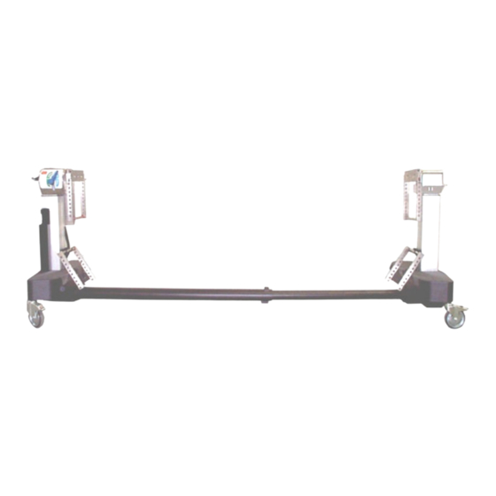
2.0 CONTROLS IDENTIFICATION 2.1 Major Component Identification The 5803 Base is designed to hold a Table Top that will provide a patient support that is free of any obstructions that might compete for space with the C-Arm. The major components of the 5803 Advanced Control Base are identified in the following figures. -
Page 7: Model Number And Serial Number
Head End Base. This label is located to the right of the ON/OFF switch as shown below. ON/OFF Power Battery Status / Fault / Power lights Switch Figure 4. Head End; ON/OFF Switch – Serial Number Label 5803 Maintenance and Repair Manual NW0422 Rev G... -
Page 8: Inspection
2. Read the Model/Serial Number Identification Label found at the Pedestal End of the base (See Figure 2.) to confirm the serial number and the input power requirements. 3. Place the 5803 Base in an area with at least 4 feet of clearance on all sides. 4. Perform Pre-Operational function check; see Section 4.0. -
Page 9: Pre-Operational Function Check
3.12. Using Hand Control, press and hold “Tilt Left” button to end of travel. Confirm the Foot-end Crossbar rotates freely. 3.13. Repeat the same when “Tilt Right” is operated. Report any malfunction to your OSI representative immediately. 5803 Maintenance and Repair Manual NW0422 Rev G... -
Page 10: Basic Operation
5.0 BASIC OPERATION The 5803 Base can be operated on AC or DC power. For AC power plug the AC Power Cord into the proper AC receptacle depending on the voltage requirements of the 5803 Base. Refer to the label at the Head End Base for input voltage requirements. The 5803 Base can also be operated on internal battery power with the Power Cord removed or not plugged into an AC receptacle. -
Page 11: Control Operation
Figure 7. Under normal operation, the ON/OFF power switch light and battery status light should be lit green and the Fault light should be dark. NOTE: If the Fault Light is lit, the 5803 Base has detected a fault. Determine fault before use. 1) 180° Rotation Lock... -
Page 12: 180°- Rotation Lock Indicator
Tilt Drive Status Indicator is illuminated. If the Head-end Crossbar is not horizontal, the internal power tilt mechanism is out of synchronization with the Crossbar. Refer to Synchronizing the Lateral Tilt Function to reset this function. 5803 Maintenance and Repair Manual NW0422 Rev G... -
Page 13: Hand Control Module
5.6 Hand Control Module Each 5803 Base is equipped with a push-button hand-held pendant control module (Hand Control), which is stored on a bracket at the Head-end. The Hand Control allows the operator to raise, lower, Trendelenburg, reverse-Trendelenburg, and laterally tilt any attached table top. The selected function will continue to operate until the button on the Hand Control is released. -
Page 14: Synchronizing The Lateral Tilt Function
Also, the Head-end Crossbar and Foot-end Crossbar can become unsynchronized (not at the same tilt angle) if a Crossbar is rotated manually or the 5803 Base is operated without a Table Top in place. The Crossbars must be synchronized to each other, as well as to the Tilt Drive- mechanism. -
Page 15: Tabletop Coupling Procedure
5.8 Tabletop Coupling Procedure The Modular Table Tops may be interchanged and coupled to the 5803 Base as needed t o provide flexibility and specific procedural capability. Position the 5803 Base and engage all four Caster Locks. Only Table Tops with Gimbals may be used with the 5803 Base. - Page 16 The Head End and the Foot End of the Table Top are normally coupled at the same hole in the H-Frame. The only exception is when extreme Trendelenburg is needed. 5803 Maintenance and Repair Manual NW0422 Rev G...
-
Page 17: Tabletop Coupling Procedure With Top In Place
Verify that the Table Top is coupled at the desired height at the Head End. 5.10 Rotation Procedures The 5803 Base provides the capability of rotating a tabletop 180°. This is a manually activated function. NOTE: At least two people are required to hold and control the rotating motion of the Table Tops. -
Page 18: Retracting The Base For Storage
NOTE: The attendant performing the Rotation may now release the Table Tops. 5.13 Retracting The Base For Storage The 5803 Base retracts from 120 inches to 73-1/2 inches for storage. To retract the Base: 1. Lock the Head End Casters and unlock the Foot End Casters. -
Page 19: Cleaning And Maintenance
No other lubrication is necessary. Table Interior: All of the internal moving parts of the 5803 Base receive factory lubrication which, under normal use, provides lubrication for the life of the equipment. 6.3 Preventative Maintenance Contact OSI Technical Service for a complete Preventative Maintenance Checklist. -
Page 20: The Electrical System
It uses AC power when plugged into a proper AC receptacle and the ON/OFF Power- switch is in the “ON” position. When not plugged in, or AC power is lost, the 5803 Base will automatically switch over to internal battery power. The batteries are automatically recharged whenever the 5803 Base is plugged into an AC power source and the ON/OFF power-switch is in the “ON”... -
Page 21: Troubleshooting
Tighten lever to Max. Check Adjust brake tension. won’t stop Rotation-Head brake band. Adjust handle to proper range. Or Foot End. Replace if necessary. Caster won’t lock/unlock Check Caster for damage. Replace Caster. 5803 Maintenance and Repair Manual NW0422 Rev G... - Page 22 Same as for tilt w/rocker on. Release button. (all functions Immediate cessation of above. Hand controller faulty, PC board except Tilt when rocker switch is No additional function. faulty. on). 5803 Maintenance and Repair Manual NW0422 Rev G...
- Page 23 Brake engages. LED turns on for PC board faulty, motor faulty, Power down. 15-25 seconds later, LED off. wring to motor disconnected, LED faulty; wiring disconnected. PC board faulty. No battery power. 5803 Maintenance and Repair Manual NW0422 Rev G...
-
Page 24: Removal And Replacement Of Components
8. Carefully slide the cover away from the base, along the tilt axis. Caution: Wires still connect the switches and lights on the cover to the base. Lifting out the 180° Rotation Lock Indicator light will help prevent damage. Figure 14: Head Cover Removal 5803 Maintenance and Repair Manual NW0422 Rev G... -
Page 25: Foot-End Cover
1. Switch off the table at the circuit breaker and disconnect the power cord from the source. 2. Unscrew Hand Control cord-connector from base receptacle. 3. Unplug Hand Control cord connector from the base. 5803 Maintenance and Repair Manual NW0422 Rev G... -
Page 26: Batteries
• Incorrectly connected batteries can cause damage to equipment or injury. Bridging (shorting) of battery terminals can cause explosion of the battery or fire. • Do not attempt to connect AC power to the 5803 Base until correct battery connection is confirmed. - Page 27 • Batteries connected properly. • Batteries have been charged. • Repeat test that all lights on Hand Control illuminate on and off sequentially and Battery Fault Light is dark. If not, contact OSI Technical Service. 5803 Maintenance and Repair Manual NW0422 Rev G...
-
Page 28: Power Supply
10. Remove the 10-32 screw underneath of the trolley in the groove at front. 11. Slide the Head End Assembly away from you and remove it from base. 12. Install replacement in the reverse order. 5803 Maintenance and Repair Manual NW0422 Rev G... -
Page 29: Head-End Tilt Motor
7. Remove the ¼-20 inch screws attaching the beam to head-end and foot-end bases. 8. Remove the center beam. 9. Install replacement in the reverse order. 9.13 Casters 1. Remove the ½- inch bolt from the outside of the base plate. 5803 Maintenance and Repair Manual NW0422 Rev G... -
Page 30: Adjustment Of Components
Retest that Rotating Crossbar resists 95 ft/lbs of rotational force in both directions using torque wrench and Rotation Test Bar P/N T5890-21-23 If test fails, repeat adjustment procedure. If test passes adjustment is complete. 5803 Maintenance and Repair Manual NW0422 Rev G... -
Page 31: Home & Tilt Left/Right Sensors
Base. Check the wiring to the head end, and if this does not alter the condition of the base, replace the controller PC Board. Figure 17: 180°- Rotation Lock Indicator Light limit switch and Lock Handle. 5803 Maintenance and Repair Manual NW0422 Rev G... -
Page 32: Head-End Slider Adjustment Procedure
10.4 Head-End Slider Adjustment Procedure Overview: With one of the OSI modular (interchangeable) table-tops attached to the Advanced Control Base, in- line movement of the Head-end Slider (or trolley assembly) is required to accommodate Trendelenburg and Reverse-Trendelenburg positioning. Periodic adjustment may be needed to maintain proper friction of movement. -
Page 33: Foot End
As the Safety Lock wears, adjustment may be required to achieve complete locking. The adjustment for this is as follows: 1. The 5803 Base should be upright. 2. Supply power to the base and turn the circuit breaker on. 3. Remove the foot end cover. -
Page 34: Rotation Safety Lock (Brake) "On" Sensor Setting
14. Turn the Rotation Safety Lock switch on. 15. Verify that the switch is closed when the motor stops. 16. Reconnect the battery wire. 17. Replace the cover underneath the foot end base casting. 5803 Maintenance and Repair Manual NW0422 Rev G... -
Page 35: Technical Drawings And Parts Lists
11.2 Table-base Assembly Bill of Materials See attached drawing at end of manual. 11.3 Replacement / Spare Parts List 1. Power Supply…………….…………….…………………..….(part number) 5803-48 2. 10 Amp Motor Control PCB………………………………………………….5803-21 3. Telescopic I-Beam Assembly…………………………………………………5803-49 4. Hand Control…………………………………………………………...……….6807-1 5. Circuit Breaker……………………………………………………….………. NV0387 6. -
Page 36: Glossary Of Terms
“Hospital Grade " outlet refers to a 120VAC outlet properly wired with earth ground: Neutral to Common = 120VAC; Neutral to Ground = 120VAC; Common to Ground less than zero point five (0.5) VAC. 5803 Maintenance and Repair Manual NW0422 Rev G... -
Page 37: Osi Technical Service
13.0 OSI TECHNICAL SERVICE 13.1 Contact for Parts and Service For detailed repair information or to order replacement parts, call the OSI Technical Services Department: 1-800-777-4674 A Technical Services line is available from 7AM-5PM PST, Monday through Friday. Please leave a message after business hours. - Page 39 5803-22 MAIN COL. WITH CONNECTORS KA0120100 1/8X1.0 ADH BACKED POLYURETHANE 60A 22 in 5803-21 10 AMP MOTOR CONTROL BOARD ASSY FOR 5803 AJ0114 RETAINING RING EXTERNAL 1" DIA, SST 5803-2 FOOT END ASSEMBLY AEO21050A #10 FLAT WASHER (.50 OD X .21 ID X .04)
- Page 40 1 APPLY BLUE LOCTITE #242 OR EQ TO THREADS PRIOR TO ASSEMBLY 2 ADJUST HEAD END TROLLEY RESISTANCE NOT SHOWN 4X TO 20-25 POUNDS BY ADJUSTING ITEM 89 NOT SHOWN 4X IN AND OUT. LOCK ITEM 89 IN PLACE WITH ITEM 65. STRIP PAINT OFF OF ITEM 18 (APPROX .5 DIA 2 PLACES) FOR GOOD GROUND CONTACT WITH SCREWS ITEM 67...
- Page 41 GREY FROM BEAM CONNECTED ORANGE FROM BEAM CONNECTED 85 2X 86 85 TO RED FROM COLUMN TO BLACK FROM COLUMN .5 FT "H" 99 5X 57 5X "ROT" "180" BLACK FROM BEAM RED FROM BEAM GROUND STUD PART SEQUENCE FROM BASE IS STAR WASHER, NUT, GROUND WIRES, STAR WASHER, NUT.
Need help?
Do you have a question about the 5803 and is the answer not in the manual?
Questions and answers