Table of Contents
Advertisement
Advertisement
Table of Contents

Summary of Contents for Kieback & Peter RPW301-FTL
- Page 1 Quick Start Guide Room Sensor Valve Controller...
-
Page 3: Table Of Contents
en:key 3/44 Important Information Symbols, signal words ................ 4 Basic safety instructions ..............5 Proper use ..................6 Wireless radio systems and health ............6 Data protection .................. 6 Device Overview Valve controller .................. 7 Room sensor ..................8 Commissioning Testing the installation location ............ -
Page 4: Important Information
Important Information en:key 4/44 I M P O R T A N T I N F O R M A T I O N This quick start guide will help you to ensure that your devices always run reliably. You must read this guide and all other applicable documents before using the devices. -
Page 5: Basic Safety Instructions
Important Information en:key 5/44 Symbol Description Symbol Description Information that prevents mal- functions and potential extra General information. work. Information on disposing of the Information on location and electronics. positioning. Information on recycling. » Basic safety instructions Read and observe the following safety instructions before using the devices. This will reduce the risk of personal injury and damage to the environment or the devices. -
Page 6: Proper Use
Important Information en:key 6/44 » Proper use The en:key room set devices are intended solely for the purpose of controlling the room temperature in closed, indoor rooms (e.g. residential and business rooms). The en:key room set is not suitable for the operation of underfloor heating. Each room requires a separate room sensor. -
Page 7: Device Overview
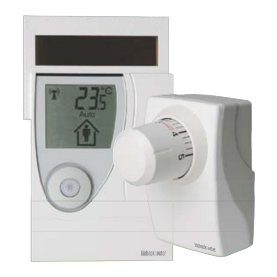
Device Overview en:key 7/44 D E V I C E O V E R V I E W » Valve controller Operating components, functional components Item Designation Explanation Rotary knob Adjusts comfort temperature → Setting the comfort temperature (S.21) Octagon nut Fastens the valve controller to the valve →... -
Page 8: Room Sensor
Device Overview en:key 8/44 » Room sensor Operating components, functional components Item Designation Explanation Display Shows information on the current state of the room sensor and valve controller Occupancy sensor Detects presence/absence for the heating time profile Solar cell Generates energy for the room sensor. Magnetic contact Switches the display between room temperature/time Starts the service level... - Page 9 Device Overview en:key 9/44 Item Designation Explanation Occupancy button Switches the room sensor on (with setting button) Temporarily changes between comfort mode/economy mode Sets time and date, vacation mode → Testing the installation location (S.12) → Changing to comfort mode/economy mode (S.22) →...
- Page 10 Device Overview en:key 10/44 Display Item Designation Explanation Antenna Wireless connection system status → System status (S.36) Battery Energy storage unit system status → System status (S.36) Windows Rapid temperature drop detected → System status (S.36) Code Status messages → System status (S.36) →...
- Page 11 Device Overview en:key 11/44 Item Designation Explanation Auto Heating time profile is active (default/learned) → Registering the valve controller (S.14) Solar cell is active (test installation location) en:key room set is in summer mode → Testing the installation location (S.12) →...
-
Page 12: Commissioning
Commissioning en:key 12/44 C O M M I S S I O N I N G » Testing the installation location In order to ensure that the occupancy sensor functions correctly, mount the room sensor at a height of approx. 1.50 m above ground level. Item Designation Explanation... - Page 13 Commissioning en:key 13/44 You want to switch on the room sensor and test an installation location for it. ►1 Press the “occupancy button” and the “setting button” simultaneously and hold them down for 5 seconds. “rEs” is displayed briefly. The “Code Δ,” “Sun,” “Occupancy” and temperature icons appear. The room sensor is switched on;...
-
Page 14: Registering The Valve Controller
Commissioning en:key 14/44 » Registering the valve controller It is not possible to disconnect individual valve controllers from the room sen- sor or register them again once a registration procedure has been com- pleted. In such cases, all the valve controllers must be registered in a new procedure. - Page 15 Commissioning en:key 15/44 ►1 Press the “occupancy button” and the “setting button” simultaneously and hold them down for 5 seconds. “rEs” is displayed briefly. The “Code Δ,” “Sun,” “Occupancy” and temperature icons appear. The room sensor is switched on; the occupancy sensor and solar cell are active.
-
Page 16: Mounting The Room Sensor
Commissioning en:key 16/44 If the valve controller acknowledges the registration with a series of tones or if “Code Δ2” appears on the display, the registration was not successful, and must be repeated. Up to 10 minutes may elapse before the first data exchange. If the room sen- sor switches off after 15 minutes, registration was not successful and must be repeated. - Page 17 Commissioning en:key 17/44 Item Designation Explanation Adhesive pad Bonds the wall mount to even surfaces Fastening material Select based on surface (Not included in scope of delivery) Adhesive digits Identifies room sensor and wall mount Holding bar Holds the room sensor in place on the wall mount Wall mount Room sensor wall fastening You want to bond or screw the wall mount to a wall.
-
Page 18: Mounting The Valve Controller
Commissioning en:key 18/44 Screws: Drill two mounting holes in the marked positions. If necessary, insert wall plugs into the mounting holes. Hold the wall mount against the wall in the marked position and screw the wall mount in place tightly, making sure that it is aligned correctly. Go to item 8. - Page 19 Commissioning en:key 19/44 Fastening the valve controller The valve controller is fastened onto the radiator valve using an octagon nut (M30x1.5 DIN 13). 10 Nm Item Designation Explanation Radiator valve Controls the heat supply for the radiator Octagon nut Fastens the valve controller to the radiator valve Rotary knob Adjusts comfort temperature Flange...
- Page 20 Commissioning en:key 20/44 You want to fasten the valve controller onto a radiator valve. ►1 Remove the old thermostat head from the radiator valve. Turn the “rotary knob” on the valve controller to the maximum setting. Ensure that the valve controller is not tilted when mounted on the “radiator valve”.
-
Page 21: Operation
Operation en:key 21/44 O P E R A T I O N » Setting the comfort temperature The time taken to reach the selected room temperature depends on the radi- ator and the size of the room. In exceptional cases, settings on the heating system or insufficient radiator size can result in the set comfort temperature not being reached. -
Page 22: Changing To Comfort Mode/Economy Mode
Operation en:key 22/44 Increasing the comfort temperature It is too cold for you, and you want to increase the comfort temperature. ►1 Turn the “rotary knob” to a higher setting. The room temperature rises to the set comfort temperature. Lowering the comfort temperature It is too warm for you, and you want to lower the comfort temperature. - Page 23 Operation en:key 23/44 Item Designation Explanation Occupancy Person outside – economy mode Changing to comfort mode You want to change to comfort mode. ►1 Briefly press the “occupancy button.” The “Occupancy” icon changes to “Person in house.” The “Auto” icon disappears. Economy mode changes to comfort mode.
-
Page 24: Start/Change/End Vacation Mode
Operation en:key 24/44 » Start/change/end vacation mode Item Designation Explanation Occupancy but- Start/change vacation mode Vacation Start display of vacation mode Duration Current duration of vacation mode Occupancy Empty house - vacation mode Code U Vacation mode display activated You want to start vacation mode for 01 to 31 days or change the specified duration. Briefly pressing the “occupancy button”... -
Page 25: Changing The Time And Date
Operation en:key 25/44 Briefly press the occupancy button in the “Vacation” start display to change to vacation mode. The “Duration” display flashes (current value). Briefly press the occupancy button to activate the “Duration” display and then press it several times until the appropriate vacation duration appears. Vacation duration: 00 to 31days. - Page 26 Operation en:key 26/44 Item Designation Explanation Occupancy but- Change/enter time and date Time/date Start display of time and date Hour/day Display of hour, day Minute/month Display of minute, month Year Display of year You want to change the time and date. Briefly pressing the “occupancy button”...
-
Page 27: Toggling The Display
Operation en:key 27/44 Press the “occupancy button” just once to confirm the displayed minute, or multiple times until the current minute appears. The “Year” display flashes after approx. 3 seconds (current year). Press the “occupancy button” just once to confirm the displayed year, or multiple times until the current year appears. -
Page 28: Restoring The Defaults
Operation en:key 28/44 Item Designation Explanation Magnet Starts toggling between room temperature/time (Not included in scope of delivery) Degrees Celsius/ Unit for information field clock Information field Room temperature or time, text You want to always see the time in the information field. ►1 Hold a magnet on the “magnet contact”... - Page 29 Operation en:key 29/44 In its delivery state, the en:key room set controls the room temperature according to the default heating time profile until a new heating time profile is taught in. Default heating time profile: Comfort mode: 6:00 AM - 8:00 PM, comfort temperature Economy mode: 8:00 PM - 6:00 AM, economy temperature Item Designation...
-
Page 30: Switching Off The Room Sensor, Valve Controller
Operation en:key 30/44 » Switching off the room sensor, valve controller The room sensor and valve controller do not consume any energy when switched off. In order for the en:key room set to automatically resume normal operation at the beginning of the next heating period, none of the devices may be switched off during the summer. -
Page 31: Activating The Service Level
Operation en:key 31/44 The room sensor is switched off, reset to the default settings and all registered valve controllers are logged off. Switching off the valve controller You want to switch off the valve controller. ►1 Press and hold the “registration button” for 5 seconds. The valve controller acknowledges a successful switch-off with a series of tones. - Page 32 Operation en:key 32/44 Item Messages Explanation 03.1 Registering of 1 to 4 valve controllers 03.2 De-registering of all registered valve controllers 03.3 ID, code Display of radio ID and number of valve controller 03.4 Switching off the room sensor 03.5 Version, code Display of software version (processors) You want to activate the service level.
- Page 33 Operation en:key 33/44 To register up to three additional valve controllers, briefly press the “registra- tion button” of the next valve controller within 15 seconds. The valve controller acknowledges startup with one signal tone shortly afterwards. The valve controller acknowledges successful registration with two signal tones.
- Page 34 Operation en:key 34/44 After de-registering the valve controllers, the room sensor switches off after 15 minutes if no other valve controller is registered. Displaying the radio ID You want to see the radio ID of the valve controller. ►1 Activate the service level and select the “ID, code” function. The figures show the last 4 digits of the radio ID (e.g.: 934F).
-
Page 35: Messages
Messages en:key 35/44 M E S S A G E S Item Icon Explanation Antenna System status, wireless connection malfunctions Battery Energy storage unit system status Windows Rapid temperature drop detected Prog Valve controllers can be registered Solar cell is active, summer mode Occupancy Presence/absence, vacation mode Code... -
Page 36: System Status
Messages en:key 36/44 » System status Icon State Explanation Antenna Fault-free radio connection Code Δ Installation location analysis is active Antenna Flashes Room sensor ready Prog Valve controller registration possible Antenna Wireless radio connection partly interrupted (> 1 hour) Code Δ1 At least one valve controller is being received Antenna Wireless radio connection interrupted (>... -
Page 37: Malfunctions
Messages en:key 37/44 » Malfunctions Icon State Explanation Antenna Transmission function malfunctioning Code Δ8 Room sensor Code Δ3 System time malfunctioning Room sensor Transmission function The room sensor continuously monitors the wireless radio connections. If a transmission malfunction is detected in the room sensor, “Code Δ8” appears. ►1 Reset the room sensor to its defaults. -
Page 38: Other
Other en:key 38/44 O T H E R » Care, disposal, service Caution Housing with a sensitive surface. Sponges and abrasive cleaning materials lead to scratches and a dulling. ► Clean using a moist, lint-free cloth. Do not use any abrasive cleaning materials or cleaning products. The room sensor and the valve controllers require no maintenance. -
Page 39: Technical Data
Other en:key 39/44 » Technical data 10,5 91,6 R 30,0 90,0 19,7 85,5... 90,5 61,8 12,5 46,5... - Page 40 Other en:key 40/44 Designation Room sensor Valve controller RPW301-FTL MD10-FTL-HE Nominal voltage 2.3 V =/0.08 W 3 V =/0.3 W Power supply Lithium battery (AA) Energy storage unit Measuring system Digital room temperature sensor Room temperature: 0 °C.. 40°C, accuracy: 0.1 K Interface EnOcean wireless protocol (<...
- Page 41 Other en:key 41/44...
- Page 42 Other en:key 42/44...
- Page 44 Saving is Fun See www.enkey.de for more information Kieback&Peter GmbH & Co. KG Tempelhofer Weg 50, 12347 Berlin Telefon 030 600 95 0 Telefax 030 600 95 164 info@enkey.de, www.enkey.de...
Need help?
Do you have a question about the RPW301-FTL and is the answer not in the manual?
Questions and answers