Table of Contents
Advertisement
Quick Links
Advertisement
Table of Contents

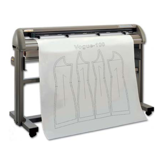
Related Manuals for Great Computer Corporation Vogue TP-183P

Summary of Contents for Great Computer Corporation Vogue TP-183P
- Page 1 Apparel plotter TP-183P User Manual Great Computer Corporation ©...
- Page 2 NOTICE GCC reserves the right to modify the information contained in this user manual at any time without prior notice; un-authorised modification, copying distribution or display is prohibited. All comments, queries or suggestions concerning this manual please consult with your local dealer.
-
Page 3: Table Of Contents
TP-183P User Manual 1. General Information 1.1 Introduction 1.2 Safety Precaution 2. Installation Stand Components Stand Installation Plotter Setup Pen Installation Cable connection 2.5.1 USB Interface 2.5.2 Parallel Interface 2.5.3 RS-232 Interface 2.5.4 Data Transmitting 3. The Control Panel The LCD Panel Menu in on-line mode Menu in off-line mode Description of menu items... -
Page 4: General Information
TP-183P User Manual 1. General Information Introduction 1.1.1 Check supplied items Please check carefully whether you have received all the items listed below. If there’s any item missing, consult your local dealer for further assistance. Apparel Plotter 1 set Stand and Paper Tack-up System 2 pieces of Side Stands 2 pieces of Stand Bases 1 piece of Stand Beam... - Page 5 TP-183P User Manual 1.1.2 Front View of TP-183P Control Panel consists of 14 control keys, 1 Drum Tool Carriage show LED, and 1 LCM to to help moving media to perform plotting with messages and menus. back and forth during the installed pen.
- Page 6 TP-183P User Manual 1.1.4 Left-Hand Side of TP-183P 【Figure 1-3】 1.1.5 Right-Hand Side of TP-183P Parallel Interface Connector to connect the plotter and a computer through a parallel interface cable. Serial Interface Connector (RS232C) to connect the plotter and a computer through a serial interface cable.
-
Page 7: Safety Precaution
TP-183P User Manual Safety Precaution Make sure the power switch is off before install the plotter. Handle the plotter carefully to prevent damages. Choose a proper place where meets the following conditions to set up the plotter The machine can be approached easily from any direction. Keep enough space for the plotter, accessories and supplies. -
Page 8: Installation
TP-183P User Manual 2. Installation This chapter describes the installation procedure of Stand and Paper Take-Up System. Stand Components Component Quantity Description Side Stand Roll holder support * 2 Control board * 1 (for Paper Take-Up System) Dancer guiders * 4 Stand Beam Paper Take-Up &... -
Page 9: Stand Installation
TP-183P User Manual Stand Installation It is recommended to assemble the stand by at least 2 people to prevent damages from dropping components onto the ground. Installation procedure: 1. Fasten 2 sets of side stand and Stand Base by supplied screws. 2. - Page 10 TP-183P User Manual Step 2 Take off the cover of control board. Step 3 The wire goes through the hole showing in Figure 2-5 to reach power board. Step 4 Plug in the head to the power connector (see the details in Figure 2-5, 2-6, 2-7 and 2-8). Cover The Wire goes through the hole...
-
Page 11: Pen Installation
TP-183P User Manual Step 5 Corrugated Pipe Put the cover back. Step 6 Wind the Corrugated Pipe around the wire for protection from electric shock (see Figure 2-9). 【Figure 2-9】 Pen Installation Penholder Upper part Penholder Lower part Refill of ink pen Spring 【Figure 2-10】... -
Page 12: Cable Connection
TP-183P User Manual 【Figure 2-12】 Cable Connection The apparel plotter communicates with a computer through a USB (Universal Serial Bus), Parallel port (Centronics) or a Serial port (RS-232C). This section shows you how to connect the apparel plotter to a host computer and how to set up the computer/apparel plotter interconnection. - Page 13 TP-183P User Manual USB driver installation Caution!! If you are using Windows 2000 / XP / Vista / 7 as your operating system, make sure you log in using the “Administrator” account. Use the USB One-click Installation for quick driver installation. Follow the simple steps below for driver setup.
- Page 14 TP-183P User Manual NOTE If you use the Windows 7 / Vista 64 bit program, please note that a pop-up window will be shown upon the initial installation as shown below: Click “Yes” to continue. (3) Click “Next” to start the driver installation. Installation...
- Page 15 TP-183P User Manual (4) The installation will take a few minutes to complete and you will see a message below and click on “OK” upon completion. Enjoy your GCC Vogue! Note: (1) If the driver is being installed for a second time, the user will be prompted as to whether a second copy of the driver installation is required.
-
Page 16: Parallel Interface
TP-183P User Manual 2.5.2 Parallel Interface Connecting to the Parallel Port (Centronics) a. Connect a parallel cable to the apparel plotter and the host computer. b. Set up the output port LPT1 or LPT2 from your software package. c. Send data to the apparel plotter directly from your software, or use DOS commands, like TYPE or PRINT, to output data. -
Page 17: The Control Panel
DATA CLEAR CUT TEST PAUSE / RESUME ENTER LINE < LCD Control Panel on Vogue TP-183P> Function LCD Screen To display functions and error messages. Power LED To indicate the power status ( light up: power on; light off: power off ) 4 Arrow Keys To move position, select function, or change setting. -
Page 18: Menu In On-Line Mode
TP-183P User Manual Menu in On-line Mode P o w e r O n V o g u e T P -1 8 3 P in p ro c e s s in g V o g u e T P -1 8 3 P L C M V e rs io n 1 .0 F irm w a re V -.-- C o p yrig h t 2 0 0 3... -
Page 19: Menu In Off-Line Mode
TP-183P User Manual Menu in Off-line Mode Press [ON/OFF LINE] to switch online and offline mode Please [Enter] to finish setup of each function. Offline For System Setup [Force Key] Force: 55 gf 0-55gram with an increment of 5 gf OK: Enter [OFFSET KEY] Non-Fubctional At This... -
Page 20: Description Of Menu Items
TP-183P User Manual Description of Menu Items Below describes the functions of menu items: Menu or Key Function Setting Default --- POWER --- to indicate the power status. [ Arrow Keys ] 1. to move the tool carriage position on X or Y axis. 2. - Page 21 TP-183P User Manual Copy: 1~99; to copy the last job without re-sending the data. 1 per step * 1mm gap will be auto-generated between 2 copies). * if the media length is not enough to continue, it will show below message on LCM:. * if both functions are enabled at the same time, the cutter will perform the last setting only.
- Page 22 TP-183P User Manual Scale Length to adjust the scale of media length and width that may cause by the thickness of the media. The Denominator is the actual length, and the Numerator is the ideal length measured from the resultant. For example, cutting a line with 500.0 mm length.
-
Page 23: Operation
TP-183P User Manual 4. Operation Paper Loading Paper Roll Step 1 Install one paper hub onto one side of paper roll. Paper Hub Step 2 Slide the feed shaft through the paper roll. Step 3 Feed Shaft Install the other paper hub onto the other end of paper roll and set it firmly/ (Figure 4.1). - Page 24 TP-183P User Manual Draw out paper from upper side of the roll. 【Figure 4-5】 【Figure 4-4】 Step 6 Fix paper on the front shaft by twin adhesive tape (Figure 4-6). Step 7 Place the two dancer bars into the dancer guiders .
- Page 25 TP-183P User Manual Adjust the Plotter For loading media properly, follow below procedures to adjust the plotter: Step 1 Use the lever on the upper right side of the plotter to raise or lower down pinch rollers. Pull the lever forward until it makes a clicking sound then the pinch rollers are raised (Figure 4-9). Lever 【Figure 4-9】...
-
Page 26: Tracking Performance
TP-183P User Manual Step 4 Push the lever backward to lower down the pinch rollers. Step 5 Turn on the power. The tool carriage will measure the media size automatically. Tracking Performance In order to achieve the best tracking performance for a long plot, it’s recommended to follow up below regulations: If the media length is less than 4 m, leave the margin of 0.5mm ~ 25mm in the left and right edges of the media (Figure 4-12). -
Page 27: Adjusting The Plotting Force
TP-183P User Manual Adjusting the Plotting Force Before sending your designs for plotting, you may perform a “cut test” to generate satisfactory plotting results. “Cut Test” should be repeated until the appropriate plotting conditions for the media are discovered. After sizing the media, press [CUT TEST] button to select the “square cut”, and press [ENTER KEY] to confirm. -
Page 28: Maintenance
TP-183P User Manual 5. Maintenance This chapter explains the basic maintenance required for the apparel plotter. All the other maintenance without mention here must be performed by a qualified service technician. Cleaning the Apparel Plotter In order to keep the apparel plotter under good condition and best performance, it’s Recommended to clean up the machine properly and regularly. -
Page 29: Cleaning The Pinch Rollers
TP-183P User Manual Cleaning the Pinch Rollers If the pinch rollers need a thorough cleaning, use a lint-free cloth or cotton swab to wipe away the accumulated dust from the rubber portion of the pinch rollers. To prevent the pinch rollers from rotating while cleaning, use finger to hold the pinch rollers not to rotate. If need to remove the embedded or persistent dust, use the lint-free cloth or cotton swab moistened with rubbing alcohol. -
Page 30: Cleaning The Pc Boards
TP-183P User Manual Step 2 Disassemble the top and side covers. Step 3 Use a bristle brush (toothbrush is acceptable) to remove dust around the X-axis and Y-axis motors (Figure 5-4 & 5-5). 【Figure 5-4】 【Figure 5-5】 Cleaning the PC boards Step 1 Turn off the apparel plotter. -
Page 31: Trouble Shooting
TP-183P User Manual 6. Trouble Shooting This chapter helps you to correct some common problems that may come across. Prior to getting into the details of this chapter, please be sure that your application environment is compatible with the apparel plotter. Note: Before having your apparel plotter serviced, please make certain that the malfunction is in your apparel plotter, not the result of an interface problem or a malfunction in your... -
Page 32: Operational Problems
TP-183P User Manual 6.2 Operational Problems Some mechanical problems or failure during operation will cause some problems. The error messages shown on the LCM present the problem first, and followed by recommended actions. If the problem still exists after the recommended actions have been done, have your apparel plotter serviced. -
Page 33: Data Communication Problems
TP-183P User Manual Data Communication Problems The messages showed below present problems in relation to apparel plotter/computer communication. Is the connection cable connected Communication Error to the apparel plotter and computer Setup: MISC. key properly? Has the interface setting been Refer to Chapter 4 - done correctly? Connecting your apparel... -
Page 34: Software Problem
TP-183P User Manual Software Problems Check the following first: Does your software package indicate that it will work with your computer and apparel plotter? Does your software support HP-GL and HP-GL/2 drivers? (* check the configuration settings of your software.) Does the apparel plotter interface Most well-known patterning software match the requirements of your... -
Page 35: Plotting Quality Problem
TP-183P User Manual Plotting Quality Problems Is the pen installed correctly and the pen holder fastened securely? Refer to Chapter 2-4 Is the pen dull or “Pen Installation”. chipped? Replace Is tool force set up with a new properly? (The default for tool force is 55 gf) Is the tool offset set up Adjust the tool force to obtain... -
Page 36: Vogue Specification
TP-183P User Manual Vogue Specification Model Name Vogue TP-183P Max. Media Loading Width 1900mm(74.8”) Min. Media Loading Width 900mm(35.4”) Max. Plotting width 1830mm(72”) Number of Pinch Rollers Max. Plotting Speed Up to 1080mm/sec (42.5 ips) Motor DC Servo Control Acceptable Pens Disposable Ink and Ball Point Pens Max. -
Page 37: Vogue Cad Output Accessory Instruction
TP-183P User Manual Vogue CAD Output Accessory Instruction Chapter 1 Vogue CAD Output Accessory(GCC plotter software、Dongle)Instruction….2 Chapter 2 The setting of GCC Plotter output……………………………………………………….4 Chapter 3 Automatic queuing function………………………………………………………………8 Vogue CAD Output Accessory Instruction... - Page 38 TP-183P User Manual Chapter 1 Vogue CAD Output Accessory(software、dongle)Instruction 1、 If you have installed previous versions of the GCC plotter software, please remove it from the control panel in your PC. 2、 Insert the installation CD and click “setup.exe”. 3、 Click “OK” to continue with the installation. 4、...
- Page 39 TP-183P User Manual 7、 Plug-in the dongle and start the GCC plotter software. You will see the window below showing that the installation has been completed correctly. Vogue CAD Output Accessory Instruction...
- Page 40 TP-183P User Manual Chapter 2 The setting of GCC Plotter output 1、 Install the Vogue driver. Install the Vogue driver and set up the ports as USB. (See Chapter 5 for details.) Please note that if you output through the printer port, you need to set up the port to LPT port; if you output by RS-232, you have to set up the port to the COM port.
- Page 41 TP-183P User Manual Note 2:Enter the length and width of the media in the corresponding fields. 4、 Click and choose to import the file (PLT format) you want to plot. Note: you can import the PLT file with different resolutions. 5、...
- Page 42 TP-183P User Manual Note: The coordinates must be a positive number or the output image might not be outputted completely. You can move the coordinates manually to ensure that the coordinates are positive and thus will be outputted correctly. 6、 Click the icon to access the window below: The following options are available: 1) Click...
- Page 43 TP-183P User Manual 3) Click to indicate the starting segment of the textile marker or continue with the last plotting job. 4)Click to output the file with a 1:1 ratio Enter the number of copies and press the Enter key to output the file. Vogue CAD Output Accessory Instruction...
- Page 44 TP-183P User Manual Chapter 3 Automatic queuing function 1、 Click Open Pool and keep GCC plotter software in the online status 2、 Copy the PLT file to C:\GCC\Spool (Assuming that the GCC plotter software has been installed in C:\ ) The files in the spool will be output automatically by the automatic queuing function.
Need help?
Do you have a question about the Vogue TP-183P and is the answer not in the manual?
Questions and answers