Table of Contents
Advertisement
Trademarks
®
®
Autel
, MaxiSys
®
MaxiCheck
are trademarks of Autel Intelligent Technology Corp., Ltd.,
registered in China, the United States and other countries. All other marks are
trademarks or registered trademarks of their respective holders.
Copyright Information
No part of this manual may be reproduced, stored in a retrieval system or
transmitted, in any form or by any means, electronic, mechanical, photocopying,
recording, or otherwise, without the prior written permission of Autel.
Disclaimer of Warranties and Limitation of Liabilities
All information, specifications and illustrations in this manual are based on the
latest information available at the time of printing.
Autel reserves the right to make changes at any time without notice. While
information of this manual has been carefully checked for accuracy, no
guarantee is given for the completeness and correctness of the contents,
including but not limited to the product specifications, functions, and
illustrations.
Autel will not be liable for any direct damages or for any special, incidental, or
indirect damages or for any economic consequential damages (including lost
profits).
IMPORTANT
Before operating or maintaining this unit, please read this manual carefully,
paying extra attention to the safety warnings and precautions.
For Services and Support:
http://pro.autel.com
www.autel.com
1-855-288-3587/1-855-AUTELUS (North America)
0086-755-8614 7779 (China)
support@autel.com
For details, please refer to the
®
, MaxiDAS
, MaxiScan
Service and Support
®
, MaxiRecorder
section in this manual.
i
®
®
, MaxiTPMS
, and
Advertisement
Table of Contents

Related Manuals for Autel MaxiLink ML619


Summary of Contents for Autel MaxiLink ML619
- Page 1 Autel will not be liable for any direct damages or for any special, incidental, or indirect damages or for any economic consequential damages (including lost profits).
-
Page 2: Safety Precautions And Warnings
Safety Precautions and Warnings To prevent personal injury or damage to vehicles and/or the scan tool, read this instruction manual first and observe the following safety precautions at a minimum whenever working on a vehicle: Always perform automotive testing in a safe environment. ... - Page 3 CONTENTS 1 GENERAL INFORMATION ..............1 (OBD) II .............. 1 OARD IAGNOSTICS (DTC ) ............1 IAGNOSTIC ROUBLE ODES (DLC) .......... 2 OCATION OF THE ONNECTOR OBD II R ..............3 EADINESS ONITORS OBD II M ............4 ONITOR EADINESS TATUS OBD II D ..................
- Page 4 DTC L ..................36 OOKUP 5 ABSSRS TESTING ................38 ..............38 IAGNOSTIC ESTING 6 PRINT AND UPDATE ................44 ....................44 RINT ....................45 PDATE 7 COMPLIANCE INFORMATION ............. 49 8 WARRANTY AND SERVICE ..............51 ..............51 IMITED ARRANTY ................
-
Page 5: General Information
General Information On-Board Diagnostics (OBD) II The first generation of On-Board Diagnostics (called OBD I) was developed by the California Air Resources Board (ARB) and implemented in 1988 to monitor some of the emission control components on vehicles. As technology evolved and the desire to improve the On-Board Diagnostic system increased, a new generation of On-Board Diagnostic system was developed. - Page 6 Figure 1-1 Location of the Data Link Connector (DLC) The DLC (Data Link Connector or Diagnostic Link Connector) is the standardized 16-cavity connector where diagnostic scan tools interface with the vehicle's on-board computer. The DLC is usually located 12 inches from the center of the instrument panel (dash), under or around the driver’s side for most vehicles.
- Page 7 OBD II Readiness Monitors An important part of a vehicle’s OBD II system is the Readiness Monitors, which are indicators used to find out if all of the emissions components have been evaluated by the OBD II system. They are running periodic tests on specific systems and components to ensure that they are performing within allowable limits.
-
Page 8: Tatus
The following monitors are to be used for compression ignition engines only: EGR System NMHC Catalyst NOx Aftertreatment Boost Pressure System Exhaust Gas Sensor PM Filter OBD II Monitor Readiness Status OBD II systems must indicate whether or not the vehicle’s PCM’s monitor system has completed testing on each component. - Page 9 OBD II Definitions Powertrain Control Module (PCM) – OBD II terminology for the on-board computer that controls engine and drive train. Malfunction Indicator Light (MIL) – Malfunction Indicator Light (Service Engine Soon, Check Engine) is a term used for the light on the instrument panel.
-
Page 10: O Peration
parameters such as engine RPM, vehicle speed, air flow, engine load, fuel pressure, fuel trim value, engine coolant temperature, ignition timing advance, or closed loop status. OBD II Modes of Operation Here is a basic introduction to the OBD II communication protocol. Mode byte: The first byte in the stream is the mode number. - Page 11 $04 High sensor voltage threshold for switch time measurement $05 Rich-to-Lean switch time in ms $06 Lean-to Rich switch time in ms $07 Minimum voltage for test $08 Maximum voltage for test $09 Time between voltage transitions in ms Mode $06 – Non-Continuously Monitored Systems test results. There are typically a minimum value, a maximum value, and a current value for each non-continuous monitor.
-
Page 12: Using The Scan Tool
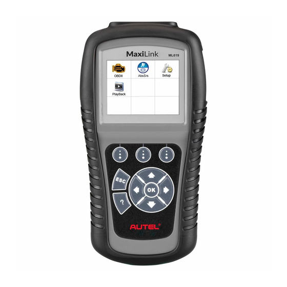
Using the Scan Tool Tool Description Figure 2-1 OBD II CONNECTOR – connects the scan tool to the vehicle’s Data Link Connector (DLC). LCD DISPLAY – indicates test results. FUNCTION BUTTONS – corresponds with “buttons” on screen for executing commands. -
Page 13: Specifications
ESC BUTTON – cancels a selection (or an action) from a menu or returns to the previous screen. LEFT SCROLL BUTTON – when looking up DTC definitions, press to review previous character and to display additional information on previous screens if present; press to view previous screen or previous frames of recorded data. -
Page 14: Power
Accessories Included User Manual – instructions on tool operations. Quick Guide – instructions on registering tool and updating software. OBDII Cable – used to connect tool to vehicle for communication and to power tool. USB Cable – used to print retrieved data. Protective Nylon Case –... -
Page 15: System Setup
System Setup The System Setup functions allow you to adjust default settings and view information about the scan tool. Language: Selects the desired language. Unit of Measure: Sets the unit of measure to English or Metric. Beep Set: Turns on/off beep. Key Test: Checks if the keyboard is working properly. - Page 16 Figure 2-4 Unit of Measure Metric is the default measurement unit. From System Setup screen, use the LEFT/RIGHT scroll button to select EN/METRIC and press the OK button. From Unit of Measure screen, use the LEFT/RIGHT scroll button to select the desired unit of measurement.
- Page 17 Figure 2-6 Press the OK button to save your selection and return to previous menu. Or, press the ESC button to exit without saving. Key Test The Key Test function checks if the keyboard is working properly. From System Setup screen, use the UP/DOWN scroll button and LEFT/RIGHT scroll button to select Key Test, and press the OK button.
-
Page 18: Vehicle Coverage
Figure 2-8 Vehicle Coverage The MaxiLink ML619 OBDII/EOBD Scanner is specially designed to work with all OBD II compliant vehicles, including those equipped with the Control Area Network (CAN) protocol. The EPA requires all domestic, Asian and European vehicles, 1996 and newer (including light trucks), sold in the United States must be OBD II compliant. -
Page 19: Product Troubleshooting
Government regulations mandate that all OBD II compliant vehicles must have a “common” sixteen-pin Data Link Connector (DLC). For your vehicle to be OBD II compliant it must have a 16-pin DLC (Data Link Connector) under the dash and the Vehicle Emission Control Information Label must state that the vehicle is OBD II compliant. - Page 20 Reset the scan tool. Turn the ignition off and wait for about 10 seconds. Turn the ignition back to on and continue the testing. Scan tool doesn’t power up If the scan tool won’t power up or operates incorrectly, do the following: ...
-
Page 21: Playback Data
Playback Data The Playback Data function allows viewing and printing data from last recorded test. Review Data Use the LEFT/RIGHT scroll button to select Playback from Main Screen, and press the OK button. Wait for the Review Data screen to appear. - Page 22 OBDII Diagnostics The OBD II Diagnostics function is a fast-access option that allows you to carry out a quick test on the engine system of OBD II vehicles. When more than one vehicle control module is detected by the scan tool, you will be prompted to select the module with retrievable data.
-
Page 23: Read Codes
Figure 4-1 If more than one module is detected, you will be prompted to select a module to test. Use the UP/DOWN scroll button to select a module and press the OK button. Read Codes The Read Codes function can be performed with the key on, engine off (KOEO) or with the key on, engine running (KOER). - Page 24 Figure 4-2 Use the UP/DOWN scroll button to select Stored Codes, Pending Codes or Permanent Codes from the Read Codes menu and press the OK button. If no codes are found, a message will display “No (pending) codes are stored in the module!” Wait a moment or press any key to return to previous screen.
-
Page 25: Erase Codes
If the manufacturer of your vehicle is not listed, use the UP/DOWN scroll button to select Other and press the OK button. Erase Codes NOTE Erasing the Diagnostic Trouble Codes may allow the scan tool to delete not only the codes from the vehicle’s on-board computer, but also “Freeze Frame”... -
Page 26: View Data
View Data The View Data function allows viewing of live or real time PID data of vehicle’s computer module(s). To view live data, use the UP/DOWN scroll button to select Live Data from Diagnostic Menu and press the OK button. Wait a few seconds while the scan tool validates the PID MAP. - Page 27 Figure 4-6 If the Merge Graph on the bottom displays when a PID is selected to view, merged graph information is available. NOTE Merge Graph can be used to compare two related parameters in graphic mode, which is especially convenient in the Custom List option where you could select two interacted parameter to merge and see their relationship.
-
Page 28: Record Data
Figure 4-8 The number to the right of selected item indicates sequence of this item. If you want to deselect the item, press Clear button. To select all the items on the screen, press Select All button. To clear all the selected items on the screen, press Clear All button. - Page 29 Figure 4-9 If you record live data under graph mode, following screen displays. Figure 4-10 NOTE The scan tool can only playback text data even though the data is saved in graphic mode. When there is not enough memory space, a warning message prompting to delete previously recorded data.
-
Page 30: Data
Select Pause to suspend recording. You could resume the recording process again by selecting Start. You may review the saved data in Playback function. Press ESC button to exit. Freeze Frame Data Freeze Frame Data allows the technician to view the vehicle’s operating parameters at the moment a DTC (Diagnostic Trouble Code) is detected. - Page 31 Retrieve I/M Readiness Status I/M Readiness function is used to check the operations of the Emission System on OBD2 compliant vehicles. It is an excellent function to use prior to having a vehicle inspected for state emissions compliance. CAUTION: By clearing trouble codes you also clear the readiness status for the individual emission system readiness tests.
- Page 32 Figure 4-13 Use the UP/DOWN scroll button to view the status of the MIL light (ON or OFF) and the following monitors. For spark ignition engines: MIS – Misfire Monitor FUEL – Fuel System Monitor CCM – Comprehensive Component Monitor ...
-
Page 33: Test
Figure 4-14 If the vehicle supports readiness test of “This Drive Cycle”, a screen of the following displays. Figure 4-15 Use the UP/DOWN scroll button for more PIDs if additional information is available on more than one page. Or use the LEFT/RIGHT scroll button to view PIDs in the previous/next page. -
Page 34: Monitor Test
The O2 Monitor Test function is not supported by vehicles that communicate using a controller area network (CAN). For O2 Monitor Test results of CAN-equipped vehicles, see On-Board Monitor Test on page 30. Use the UP/DOWN scroll button to select O2 Monitor Test from Diagnostic Menu and press OK button. - Page 35 emission-related power train components and systems that are not continuously monitored. The On-Board Monitor Test for CAN-equipped vehicles retrieves and displays test results for emission-related power train components and systems that are and are not continuously monitored. The scan tool allows access to the results of on-board diagnostic monitoring tests for specific components/systems.
- Page 36 If the vehicle being tested does not support the mode, an advisory message will display on the screen. For CAN-equipped vehicles, test selections can be as depicted below. Figure 4-19 Use the UP/DOWN scroll button to select the desired monitor from On-Board Mon.
-
Page 37: Test
Press ESC button to return to the previous menu. Component Test The Component Test function initiates a leak test for the vehicle's EVAP system. The scan tool itself does not perform the leak test, but commands the vehicle's on-board computer to start the test. Different vehicle manufacturers might use different criteria and methods for stopping the test once it has been started. -
Page 38: View Vehicle Information
Figure 4-24 Wait a few seconds or press any key to return to previous screen. View Vehicle Information The Vehicle Info. function enables retrieval of Vehicle Identification No. (VIN), Calibration ID Nos. (CINs), Calibration Verification Nos. (CVNs) and In-use Performance Tracking on 2000 and newer vehicles that support Mode 9. -
Page 39: Resent
Figure 4-26 View retrieved vehicle information on screen. Figure 4-27 Press the ESC button to return to previous menu. Modules Present Modules Present function displays the module communication protocols for OBD II modules in the vehicle. Use the UP/DOWN scroll button to select Modules Present from Diagnostic Menu and press OK button. -
Page 40: Dtc Lookup
Press the ESC button to return to previous menu. DTC Lookup The DTC Lookup function provides descriptions of DTCs and helpful tips to resolve DTCs. It is useful for technicians to find the root cause of trouble code faster resulting in reduced diagnosis and repair time. Use the UP/DOWN scroll button to select DTC Lookup from Diagnostic Menu and press OK button. - Page 41 Figure 4-31 Use the LEFT/RIGHT scroll button to view the previous / next DTC. Select Save to record code definition. For manufacturer specific codes, you need to select a vehicle make on an additional screen to look for DTC definitions. ...
-
Page 42: Abssrs Testing
Malfunction Indicator Light (MIL) to turn on. NOTE Autel accepts no responsibility for any accident or injury arising from servicing the ABS/SRS systems. When interpreting DTCs retrieved from the vehicle, always follow the manufacturer’s recommendation for repair. - Page 43 Turn on the scan tool and wait for the Main Screen to appear. Select AbsSrs icon in the Main Screen. Select a specific vehicle manufacture’s regional coverage. Figure 5-1 From the vehicle make screen, select a specific vehicle manufacture and press OK button. Figure 5-2 There are two ways for users to perform diagnostic testing system either automatically or manually:...
- Page 44 NOTE You may not need to make all the selections, or have to select other features. For some vehicles, the tool will not ask for any information before turning to the Function menu. Use the UP/DOWN scroll button to select the desired control module from the retrieved engine data menu (in GM’s case, the selected engine model: 3.6 L (LFX)), and press the OK button.
- Page 45 A screen message will prompt up to inquire the accuracy of the Vehicle Specification, if the information is correct select the Yes option to continue, otherwise select the No option on the screen to exit without saving. Enter correct Vehicle Identification Number (VIN) in the INPUT DATA menu.
- Page 46 NOTE The data you input must be in the reasonable range, which is defined by the preset values in VIN. If you enter a data out of range, the tool will display a warning message. Figure 5-5 Follow screen instruction to save vehicle information in the Input Dialog Box and Vehicle Specification sections by selecting Yes option, or No option to exit without saving.
- Page 47 11) Select the Control Unit entry to enter the System Menu option screen, and choose the desired Control Module entry for DTC information stored in the vehicle’s on-board computer. Figure 5-8 If there is not any Diagnostic Trouble Code, the display indicates “No (pending) codes are stored in the module!”...
-
Page 48: Print And Update
Windows-based computer. Connect the tool to the computer using the supplied USB cable. Run Autel Printer software on the computer. Select Playback on the Main Screen of the tool. On the data menu screen, select Print Data and then select the data you want to print. -
Page 49: Update
If you already have an Autel account, Sign In with your account ID and password. If you are a new member to Autel, click on the Create Autel ID button on the left side of the screen to create an ID. - Page 50 Run the Maxi PC Suite. Wait for the Log In window to display. Figure 6-2 Sample Log In Window Enter your Autel ID and password and wait for the Update window to display. If you forget your password, click the [Forget Password?] link to our website and retrieve your password.
- Page 51 Or, click on the Select All checkbox on the bottom left of screen and all updatable items will be selected. Click the Update All button on the right of the screen. When the download is completed, the programs will be automatically installed.
- Page 52 The deleted program(s) will be added to the end of the program list on the Update page to install again if you wish. In the search box on the top right corner of the screen, you can search the listed.
-
Page 53: Compliance Information
Compliance Information FCC COMPLIANCE This device complies with Industry Canada’s licence-exempt RSSs. Operation is subject to the following two conditions: This device may not cause harmful interference. This device must accept any interference received, including interference that may cause undesired operation. Cet appareil est conforme aux CNR exempts de licence d’Industrie Canada. - Page 54 – Connect the equipment into an outlet on a circuit different from that to which the receiver is connected. – Consult the dealer or an experienced radio/TV technician for help. Changes or modifications not expressly approved by the party responsible for compliance could void the user’s authority to operate the equipment.
-
Page 55: Warranty And Service
Limited One Year Warranty Autel Intelligent Technology Corp., Ltd. (the Company) warrants to the original retail purchaser of this Autel device that should this product or any part thereof during normal usage and under normal conditions be proven defective in material or workmanship that results in product failure within 1... -
Page 56: S Ervice And S Upport
Service and Support If you have any questions regarding the product, please contact one of our offices in your region. AUTEL NORTH AMERICA Phone: 855-AUTEL-US (855-288-3587) Mon.-Fri.9am-6pm EST Website: www.autel.com Email: ussupport@autel.com... - Page 57 AUTEL AUSTRALIA Phone: 03 9480 2978 / +61 476293327 Website: www.autel.com.au Email: sales@autel.com.au Address: 155 Islington Street, Melbourne, Collingwood, VIC For technical assistance in other markets, please contact your local tool distributor.
Need help?
Do you have a question about the MaxiLink ML619 and is the answer not in the manual?
Questions and answers
Can Maxilink ML619 be used to clear TPMS light on a vehicle.
No, the Autel MaxiLink ML619 cannot be used to clear the TPMS (Tire Pressure Monitoring System) light. It is designed to read and clear codes related to the engine (MIL), ABS, and SRS systems, but there is no mention of TPMS functionality.
This answer is automatically generated