Table of Contents
Advertisement
ECO•IQ
#N9195
™
5-2 Programmable Electronic Thermostat Heat/Cool
®
Termostato electrónico programable de calefacción/enfriamiento 5-2
Installation & OPERATING
(PAGES 1-24)
INSTALACIÓN E INSTRUCCIONES
DE OPERACIÓN
(PAGES 25-48)
Downloaded from
www.Manualslib.com
manuals search engine
Advertisement
Table of Contents

Summary of Contents for Niagara ECO-IQ N9195
- Page 1 ECO•IQ #N9195 ™ 5-2 Programmable Electronic Thermostat Heat/Cool ® Termostato electrónico programable de calefacción/enfriamiento 5-2 INSTALLATION & OPERATING INSTRUCTIONS (PAGES 1-24) INSTALACIÓN E INSTRUCCIONES DE OPERACIÓN (PAGES 25-48) Downloaded from www.Manualslib.com manuals search engine...
- Page 2 Compatible with low voltage single stage gas, oil or electric heating or cooling systems and single stage heat pumps. For use on 24VAC systems (not to exceed 30VAC) and 250mv to 750mv millivolt heating only systems. WARNING! • To prevent electrical shock and/or equipment damage, disconnect electric power to system at main fuse or circuit breaker box until installation is complete.
- Page 3 SPECIFICATIONS Electrical Rating 24 Volt AC (18-30 VAC) 1 Amp Maximum per Terminal 2 Amps Total Load Control 1 Heat / 1Cool Single Stage Heat Pump Set Point Range 45°F – 90°F (7.0°C – 32.0°C) Program 5 - 2 (Mon-Tue-Wed-Thur-Fri) & (Sat-Sun) Set Points Morn, Day, Eve, Night Advanced Recovery...
- Page 4 INSTALLATION REMOVING THE EXISTING THERMOSTAT 1. CAUTION: Make certain the power to the system has been disconnected. 2. Remove the cover of the old thermostat and locate the wires that are connected to the terminal board. IMPORTANT: Before removing these wires, NOTE (ON A PIECE OF PAPER) THE COLOR OF EACH WIRE AND THE CORRESPONDING TERMINAL MARKING ON THE OLD THERMOSTAT.
- Page 5 INSTALLATION 7. Secure the back plate to the wall with the supplied screws making certain the thermostat wires have been inserted through the large rectangular hole in the back plate. 8. Carefully attach the thermostat wires to the appropriate connections on the terminal board on the back plate. Use the notes taken from step 2 of “Removing The Existing Thermostat”...
- Page 6 Downloaded from www.Manualslib.com manuals search engine...
- Page 7 CONTROLS FUNCTION Increase temperature Press and hold both keys to access Key Lock Setting mode. Decrease temperature TIME/DAY 1. Enter Time setting mode and select hour, minute and day setting. 2. Select program time in Program setting mode. 3. Set Day in Vacation hold. PROGRAM 1.
- Page 8 Downloaded from www.Manualslib.com manuals search engine...
- Page 9 LCD DISPLAY ICON INDICATES Heating system is being activated A/C cooling system is being activated Key Lock mode is activated Battery levels Change filter reminder Vacation mode Indicates timeframe of current day (Morning, Day, Evening, Night) Indicates day of week (Monday, Tuesday, Wednesday, Thursday, Friday, Saturday, Sunday) Downloaded from www.Manualslib.com...
- Page 10 INSTRUCTIONS TESTING THE NEW THERMOSTAT WARNING! • Do not switch the system to cool if the outdoor temperature is below 50°F (10°C). This may damage the cooling system and may cause personal injury. • This thermostat is equipped with automatic compressor protection to prevent damage due to short cycling. The short cycle protection provides a 5-minute delay between heating (heat pump models) or cooling cycles to prevent the compressor from being damaged.If the Heat/Cool icon is flashing, this indicates the system is ...
- Page 11 INSTRUCTIONS 5. Set the system switch to the OFF position. The system should shut down within several seconds. The LCD will again alternately display the time and room temperature. 6. Set the system switch to the COOL position and depress the blue arrow key until the temperature set point is at least 3 degrees below the room temperature.
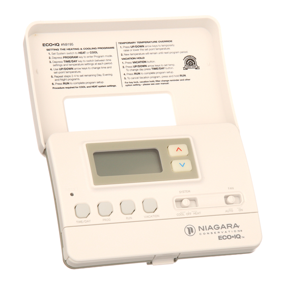
- Page 12 INSTRUCTIONS SETTING THE HEATING & COOLING PROGRAMS The thermostat includes a factory set program that will adjust the temperature 4 times per day (MORN, DAY, EVE, NIGHT) Monday through Friday and Saturday/Sunday. This program can be customized using the steps below. Factory Set Program PROGRAM SYSTEM...
- Page 13 INSTRUCTIONS CUSTOMIZING THE PROGRAM 1. Set the System switch to the HEAT or COOL position and the Fan switch to either the AUTO or ON position. NOTE: In AUTO, the system blower will run only when the A/C or heat is running. In ON, the system blower will operate continuously.
- Page 14 INSTRUCTIONS TEMPORARY HOLD 1. Use the red/blue arrow keys to temporarily raise or lower the set point temperature at any time during normal operation. The temperature will hold at the new level UNTIL the next program period begins at which point the thermostat will return to the program temperature.
- Page 15 INSTRUCTIONS CHANGE SET TEMPERATURE 1. The system switch must be set to COOL or HEAT to adjust the set temperature. 2. If the key is pressed once and released, the set temperature will increase or decrease by one degree. Press and hold the key to scroll to desired temperature and release.
- Page 16 INSTRUCTIONS Disable or Resetting the Key Lock To disable the Key Lock feature or change the code, the user must disable the LOCK first. 1. Press and hold UP and DOWN key together for 2-3 seconds to enter Key Lock Setting mode 2. “- - - “ will appear on the LCD with “lock” icon flashes 3. Enter the 3-digit code created to lock the thermostat. Press the UP or DOWN keys to select the first digit, then press PROG to move to the next digit and repeat until your 3-digit code is displayed.
- Page 17 FEATURES • Low Temperature Protection: While in the HEAT position, if the room temperature drops below 40°F (4°C), the thermostat will automatically initiate a call for heat. • Compressor Protection: To protect the system compressor(s) from damage, the thermostat features a 5-minute delay.
- Page 18 TROUBLESHOOTING SYMPTOM CORRECTIVE ACTION Display is Blank Check thermostat wiring & connections. Check circuit breaker/fuse panel. No heat Set system switch to HEAT and raise set point above room temperature. If flame icon is blinking, allow the 5 minute compressor lock-out to expire. Check thermostat wiring and connections. Check pilot light or HSI system on furnace. No Cool Set system switch to COOL and lower set point below room temperature.
- Page 19 TROUBLESHOOTING SYMPTOM CORRECTIVE ACTION ‘HI’ is displayed Reduce room temperature or allow a newly installed thermostat to acclimate. HI indicates a room temperature reading greater than 90°F (32°C). ‘LO’ is displayed Increase room temperature or allow a newly installed thermostat to acclimate. LO indicates a room temperature reading less than 45°F (7°C).
- Page 20 WIRING DIAGRAMS TERMINALS Non-Heat Pump Non-Heat Pump 2-wires millivolt Single Stage Heat Pump System* + Terminal 4-wire System* 5-wire System Heat System — Cooling 24VAC — — 24VAC Heating 24VAC Millivolt Heating 24VAC 24VAC Common 24VAC Common Transformer Common 24VAC Common —...
- Page 21 WIRING DIAGRAMS Downloaded from www.Manualslib.com manuals search engine...
- Page 22 WIRING DIAGRAMS Switch <—> sw 1 Switch <—> Switch <—> sw 5 sw 2 Switch <—> Downloaded from www.Manualslib.com manuals search engine...
- Page 23 WIRING DIAGRAMS SWITCH FUNCTION DEFAULT SETTING ON/OFF Switch should always be set to ON to avoid any system problems. Sets the display in either Celsius or Fahrenheit. (Fahrenheit) HE/HG Configure the thermostat for gas/oil or electric heating systems. For electric, set the switch to HE. For gas, set the switch to HG.
- Page 24 For warranty claims, consumers should contact the contractor or dealer who installed the thermostat. This warranty and Niagara Conservation’s liability does not include damage to merchandise or thermostat resulting from accident, alteration, neglect, misuse, improper installation, or any other failure to follow Niagara Conservation’s installation and operating instructions.
Need help?
Do you have a question about the ECO-IQ N9195 and is the answer not in the manual?
Questions and answers
When you set thermostat to factory setting by depressing as instructed do you need to do anything else
After setting the Niagara ECO-IQ N9195 thermostat to factory settings, the following additional steps are needed:
1. Attach the Thermostat Body: Align the thermostat body with the back plate by resting it on the upper clips and pressing it until the bottom locking tab snaps into place. Ensure the terminal board pins are properly aligned.
2. Set the SYSTEM Switch: Move the SYSTEM switch on the front face to the OFF position.
3. Set the FAN Switch: Move the FAN switch on the front face to the AUTO position.
4. Configure Switch Settings:
- SW1 (C/F): Set the display to Celsius or Fahrenheit as needed.
- SW2 (HE/HG): Configure for gas/oil (HG) or electric (HE) heating systems.
- SW5 (Norm/HP): Select normal heating/cooling (Norm) or heat pump system (HP).
5. Set Time and Day: Enter Time setting mode to adjust the hour, minute, and day.
6. Program the Thermostat: Enter Program setting mode to configure the desired schedule.
These steps ensure proper operation after resetting the thermostat.
This answer is automatically generated
It’s blowing hot air my apartment is at 93 and it very hot
The AC unit is not cooling properly. It’s not cooling down in the house.
I can't get the thermostat back to Fahrenheit a tenant changed it and I can't find the way to get it back to Fahrenheit