Table of Contents
Advertisement
Flexfiller Digital Pressurisation Equipment
Flexfiller Models (125D, 225D, 150D, 250D, 280D)
Midi Models (125D, 225D, 150D, 250D)
Mini Models (130D, 230D)
Operation & Maintenance
Manual
Rev 8.3
© 2014 Flamco group. All rights reserved.
.
We reserve the right to change designs and technical specifications of our products
Rev 8.1 Aug-15
Page 1 / 44
www.flamcogroup.com
Advertisement
Table of Contents

Summary of Contents for flamco Flexfiller 125D
- Page 1 Midi Models (125D, 225D, 150D, 250D) Mini Models (130D, 230D) Operation & Maintenance Manual Rev 8.3 © 2014 Flamco group. All rights reserved. We reserve the right to change designs and technical specifications of our products Rev 8.1 Aug-15 Page 1 / 44 www.flamcogroup.com...
- Page 2 Purchase From: Note: It is highly recommended to have this equipment commissioned by a Flamco approved engineer. Any damage or loss incurred through incorrect commissioning by an unapproved engineer will not be covered by the warranty. If you wish for Flamco to arrange this please contact us. (See contact details) Please see the warranty section for details.
- Page 3 Notes: Engineer Signature: Date: Customer Signature: Date: Commissioning certificate can be obtained please contact Flamco representative © 2014 Flamco group. All rights reserved. We reserve the right to change designs and technical specifications of our products Rev 8.1 Aug-15 Page 3 / 44...
- Page 4 Mini Models (130D, 230D) Troubleshooting 35 - 37 Service Log 38 - 39 Warranty Information © 2014 Flamco group. All rights reserved. We reserve the right to change designs and technical specifications of our products Rev 8.1 Aug-15 Page 4 / 44 www.flamcogroup.com...
-
Page 5: About This Manual
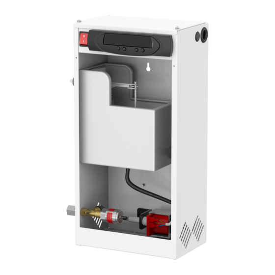
<Inequality Symbols> A message/fault code displayed on the digital controller Where to find more Information For further information please visit the Flamco Limited Website at the following URL: www.flamco.co.uk Alternatively, please contact the Flamco Limited head office using the details below:... - Page 6 The pump(s) are fitted with non-return valves (10a, 10b) to prevent backflow. A drain valve (11) is provided for draining down the unit and for commissioning purposes. © 2014 Flamco group. All rights reserved. We reserve the right to change designs and technical specifications of our products Rev 8.1 Aug-15...
-
Page 7: Pipe Connections
This point of connection should be in the system return, on the suction side of the circulation pump. Typical Installation Diagram © 2014 Flamco group. All rights reserved. We reserve the right to change designs and technical specifications of our products Rev 8.1 Aug-15 Page 7 / 44 www.flamcogroup.com... - Page 8 To install the flow restrictor/filter, hold it by the tab and push it into the opening of the float valve connection, as shown in the diagram below: © 2014 Flamco group. All rights reserved. We reserve the right to change designs and technical specifications of our products Rev 8.1 Aug-15...
-
Page 9: Flexfiller Clearance And Connection Requirements
Non-return valves, pressure reducing valves and RPZ valves must not be used. © 2014 Flamco group. All rights reserved. We reserve the right to change designs and technical specifications of our products Rev 8.1 Aug-15 Page 9 / 44... -
Page 10: Midi Clearance And Connection Requirements
Non-return valves, pressure reducing valves and RPZ valves must not be used. © 2014 Flamco group. All rights reserved. We reserve the right to change designs and technical specifications of our products Rev 8.1 Aug-15 Page 10 / 44... -
Page 11: Mini Clearance And Connection Requirements
Non-return valves, pressure reducing valves and RPZ valves must not be used. © 2014 Flamco group. All rights reserved. We reserve the right to change designs and technical specifications of our products Rev 8.1 Aug-15 Page 11 / 44... -
Page 12: Electrical Power Supply
This equipment can be damaged by the high voltages produced by electrical installation testing equipment. When performing electrical installation tests, the equipment must be isolated from the supply. © 2014 Flamco group. All rights reserved. We reserve the right to change designs and technical specifications of our products Rev 8.1 Aug-15 Page 12 / 44 www.flamcogroup.com... -
Page 13: Fault Contacts
With the exception of the Common Alarm, it is possible to convert all other fault contacts to normally closed. For further information please refer to the commissioning section of this manual. © 2014 Flamco group. All rights reserved. We reserve the right to change designs and technical specifications of our products Rev 8.1 Aug-15... - Page 14 Commissioning It is highly recommended to have this equipment commissioned by a Flamco approved engineer. Any damage or loss incurred through incorrect commissioning by an unapproved engineer will not be covered by the warranty. Pre-Commissioning Checklist The following conditions must be met before starting the commissioning process. Failure to meet these conditions may result in injury or damage to the equipment, system and property.
-
Page 15: Controller Overview
MUTE Mute Audible Alarm Reset Unit Enter Programming Menu Enter Programming Menu © 2014 Flamco group. All rights reserved. We reserve the right to change designs and technical specifications of our products Rev 8.1 Aug-15 Page 15 / 44 www.flamcogroup.com... -
Page 16: Controller Programming
To confirm all changes, the end of the menu must be reached, and the “SAVING...” message must be displayed. © 2014 Flamco group. All rights reserved. We reserve the right to change designs and technical specifications of our products Rev 8.1 Aug-15 Page 16 / 44 www.flamcogroup.com... -
Page 17: Program List
PUMP 1 HOURS engineer’s code, the counter can be reset to zero by holding the (MUTE) button. © 2014 Flamco group. All rights reserved. We reserve the right to change designs and technical specifications of our products Rev 8.1 Aug-15 Page 17 / 44 www.flamcogroup.com... - Page 18 If these settings appear to have been reset, the most likely cause is a power spike. If this problem persists, a power filter may be required. © 2014 Flamco group. All rights reserved. We reserve the right to change designs and technical specifications of our products Rev 8.1 Aug-15...
- Page 19 Disabling this option will stop the controller from monitoring the pumps and generating <PUMP FAIL> faults. PUMP SENSE It is not recommended to disable this option. Please consult Flamco Technical before doing so. The type of pressure sensor installed in the unit.
-
Page 20: Hydraulic Commissioning
Failure to do this may cause injury or damage to the equipment, system or property. Un-screw cap turn cap push cap on socket Twist cap © 2014 Flamco group. All rights reserved. We reserve the right to change designs and technical specifications of our products Rev 8.1 Aug-15 Page 20 / 44 www.flamcogroup.com... - Page 21 Do not use excessive force when tightening the bleed screw as this may damage the pump casing. © 2014 Flamco group. All rights reserved. We reserve the right to change designs and technical specifications of our products Rev 8.1 Aug-15 Page 21 / 44 www.flamcogroup.com...
- Page 22 Failure to bleed the pumps may result in damage to the equipment, system and property. After bleeding the pumps, close the drain valve and remove the hose from the hose tail. © 2014 Flamco group. All rights reserved. We reserve the right to change designs and technical specifications of our products Rev 8.1 Aug-15...
-
Page 23: Operation
Once the required system pressure has been reached, the controller will display the current system pressure. The unit is now in normal operation. © 2014 Flamco group. All rights reserved. We reserve the right to change designs and technical specifications of our products Rev 8.1 Aug-15... -
Page 24: Operation
4 x 1000 Midi Mini All Flamco vessel are set at the pre-charge (Factory set) in order for the vessel to work properly with the pressurisation unit the cold fill pressure needs to be same. Remember to check vessel pressure before commissioning... -
Page 25: Fault Codes
For practical guidance on diagnosing and rectifying faults, please refer to the Troubleshooting section of this manual. © 2014 Flamco group. All rights reserved. We reserve the right to change designs and technical specifications of our products Rev 8.1 Aug-15 Page 25 / 44 www.flamcogroup.com... -
Page 26: Shutdown Procedure
6. Depending on the conditions in the system, the unit may display one or more fault codes at this point. If this happens, please refer to the Troubleshooting section of this manual for guidance. © 2014 Flamco group. All rights reserved. We reserve the right to change designs and technical specifications of our products Rev 8.1 Aug-15... - Page 27 If the unit is a twin pump model, this test should be repeated until both pumps have run and successfully re- pressurised the system. © 2014 Flamco group. All rights reserved. We reserve the right to change designs and technical specifications of our products Rev 8.1 Aug-15...
- Page 28 If any faults are identified during these checks, please refer to the Troubleshooting section of this manual. If replacement parts are required, please refer to the Spares section for part codes. © 2014 Flamco group. All rights reserved. We reserve the right to change designs and technical specifications of our products Rev 8.1 Aug-15...
-
Page 29: Wiring Diagram
Wiring diagram © 2014 Flamco group. All rights reserved. We reserve the right to change designs and technical specifications of our products Rev 8.1 Aug-15 Page 29 / 44 www.flamcogroup.com... -
Page 30: Wiring Location
Wiring location list © 2014 Flamco group. All rights reserved. We reserve the right to change designs and technical specifications of our products Rev 8.1 Aug-15 Page 30 / 44 www.flamcogroup.com... -
Page 31: Spare Parts
5 Amp Fuse BSS R031 6.3 Amp Slow Blow Fuse (PQA90 Pumps Only) FC324 © 2014 Flamco group. All rights reserved. We reserve the right to change designs and technical specifications of our products Rev 8.1 Aug-15 Page 31 / 44... - Page 32 Mesh Strainer Float Switch BSS RO12 10 ¼” Ball Valve BSS M005 © 2014 Flamco group. All rights reserved. We reserve the right to change designs and technical specifications of our products Rev 8.1 Aug-15 Page 32 / 44 www.flamcogroup.com...
- Page 33 FCCG NO Overflow Connection BSS M021 Mesh Strainer Float Switch BSS R012 © 2014 Flamco group. All rights reserved. We reserve the right to change designs and technical specifications of our products Rev 8.1 Aug-15 Page 33 / 44 www.flamcogroup.com...
-
Page 34: Mini Models (130D, 230D)
12 ¼” Brass Locking Nut BSS M006 13 Flexible Pump Support BSS M022 © 2014 Flamco group. All rights reserved. We reserve the right to change designs and technical specifications of our products Rev 8.1 Aug-15 Page 34 / 44... -
Page 35: Troubleshooting
The unit is undersized for the system Review unit selection The FLOOD LIMIT time is too short. Consult Flamco © 2014 Flamco group. All rights reserved. We reserve the right to change designs and technical specifications of our products Rev 8.1 Aug-15 Page 35 / 44... - Page 36 (mini and midi units becoming air-locked selection (mini and midi units only) only) © 2014 Flamco group. All rights reserved. We reserve the right to change designs and technical specifications of our products Rev 8.1 Aug-15 Page 36 / 44...
- Page 37 SERVICE is displayed on the The unit is due an annual service Contact service engineer screen © 2014 Flamco group. All rights reserved. We reserve the right to change designs and technical specifications of our products Rev 8.1 Aug-15 Page 37 / 44...
-
Page 38: Service Log
Service Logs This service log should be completed by the service engineer after each annual service. © 2014 Flamco group. All rights reserved. We reserve the right to change designs and technical specifications of our products Rev 8.1 Aug-15 Page 38 / 44... - Page 39 © 2014 Flamco group. All rights reserved. We reserve the right to change designs and technical specifications of our products Rev 8.1 Aug-15 Page 39 / 44 www.flamcogroup.com...
- Page 40 If the unit is identified with a manufacturing defect then no charge is made for correcting the defect. The Flamco equipment is manufactured to order and is clearly marked, where applicable, with a unique serial number, allowing traceability to both individual model configuration and the engineer or site responsible for the build and test.
- Page 41 Notes © 2014 Flamco group. All rights reserved. We reserve the right to change designs and technical specifications of our products Rev 8.1 Aug-15 Page 41 / 44 www.flamcogroup.com...
- Page 42 Notes © 2014 Flamco group. All rights reserved. We reserve the right to change designs and technical specifications of our products Rev 8.1 Aug-15 Page 42 / 44 www.flamcogroup.com...
- Page 43 Notes © 2014 Flamco group. All rights reserved. We reserve the right to change designs and technical specifications of our products Rev 8.1 Aug-15 Page 43 / 44 www.flamcogroup.com...
- Page 44 Merseyside WA10 6PB United Kingdom T +44 1744 744 744 F +44 1744 744 700 © 2014 Flamco group. All rights reserved. info@flamco.co.uk We reserve the right to change designs and technical specifications of our products Rev 8.1 Aug-15 Page 44 / 44...
Need help?
Do you have a question about the Flexfiller 125D and is the answer not in the manual?
Questions and answers