
Summary of Contents for Avolites ART2000 T4
- Page 1 ART2000 T4 4 module Digital Dimming System Operator’s Manual software version OS3R1 Stock number 8200-0152 *82000152*...
- Page 2 ART2000 even if Avolites Ltd. has been advised of the possibility of such damages. Because some jurisdictions do not allow the exclusion or limitation of liability for consequential or incidental damages, the above limitation may not apply to you.
- Page 3 C O N T E N T S THE ART2000 DIGITAL DIMMING SYSTEM FEATURES OF THE ART2000 INSTALLING THE ART2000 SETTING USER OPTIONS ELDC OPTION ONE PHASE PER MULTIPIN OUTLET TROUBLESHOOTING INTRODUCTION TO DMX SYSTEM SPECIFICATION 10. CONNECTOR PINOUTS 11. GLOSSARY OF TECHNICAL TERMS 12.
-
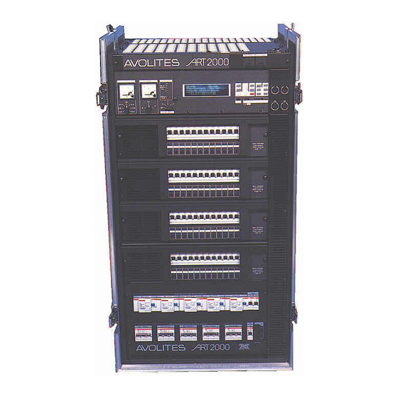
Page 4: The Art2000 Digital Dimming System
INTRODUCTION The ART2000 digital dimming system This manual is designed to help you get the most out of your Avolites ART2000 digital dimming system. Even if you hate reading manuals, read this section because the next couple of pages contain some important safety information which you should be aware of. - Page 5 Do not operate the system with any dimmer modules missing because this makes live parts accessible. Blanking plates are available from avolites to allow modules to be removed and the rack used. If you do want to use the system with a module removed fit the blanking plate (Avolites part number 17-80-0129) If Cam-lok...
-
Page 6: Features Of The Art2000
Page 6 - 2. Features of the ART2000 Features of the ART2000 This chapter gives a quick rundown on what each part of the ART2000 rack does. If you are new to the system, read this! Some Parts described in this manual may not output connectors be on the system before you, this is because the ART2000 system can be supplied from the... - Page 7 (220V). The optional series patch is labelled clearly to be series (110V) For the occasional 110V lamp Avolites has a custom Wieland series lead, part number 03-13-0040 The rear half of the panel has 20 sets of six connectors, one set for each of the multipin outlets on the rear of the rack.
-
Page 8: Installing The Art2000
Page 8 - 3. Installing the ART2000 channel dimmer module. 12x16A Breaker module: Mains distribution modules provide static power, which can be routed through the hot-patch bay and down the multicore cables, usually used to power intelligent lighting. The module has 12 channels of mains power, which can be manually switched using the front circuit breakers. -
Page 9: Power Supply
3. Installing the ART2000 - Page 9 temporary or permanent operation. Positioning the ART2000 rack Choose a location for the rack which is as near to the power feed as possible and allows access to the front and back of the rack. Consider how the cables will run in from the power feed and out to the lights, and try to avoid crossing walkways. - Page 10 Page 10 - 3. Installing the ART2000 ART2000 (TN-S) which is capable of delivering the amount of power required to run all the lights which are connected to it. If the power supply is under-rated it may trip during your show if you turn too many lights on at once.
- Page 11 3. Installing the ART2000 - Page 11 If the display shows other messages, this may indicate that a problem has been found. See the Troubleshooting section on page 24 for details of what to do. If you cannot read the display you may need to adjust the display contrast control at the bottom right hand corner of the display.
- Page 12 Page 12 - 3. Installing the ART2000 on multipin connector 1. You can check if a circuit is working by plugging the patch cable into the lamp test socket rather than a module outlet. If the circuit is OK the lamp test light will come on. You should also see the indicator lights on the channels come on when you connect a load to them.
-
Page 13: Setting User Options
4. Setting user options - Page 13 Setting user options The ART2000 has a simple user interface. Each function has its own button, shown on the right, so you don’t get lost in multiple menus. This section describes how to configure the ART2000 rack to your requirements. - Page 14 Page 14 - 4. Setting user options Viewing the dimmer levels You can view the output levels of the dimmer channels by pressing the LEVEL button (above the STORE button). The display shows the output levels as a bank of numbers. Line A 001 Dmx ok Line B 001 No Dmx Status Running ok Mode Test Off...
- Page 15 4. Setting user options - Page 15 Select the curve setting you want for that channel using the UP/DOWN buttons, then press Enter. The display looks like this: Line A 001 Dmx ok Line B 001 No Dmx Status Running OK Mode Test Off ------------------------------------------ Change dimmer channel curve...
- Page 16 Page 16 - 4. Setting user options 4.4.1 Setting the dimmer limit Press the LIMIT button Select the channel you want to set using the UP / DOWN buttons, then press ENTER. Select the Limit you want for that channel using the UP/DOWN ...
- Page 17 4. Setting user options - Page 17 Bay 4 6x 32A dimmer Dimmer channel 19-24 The main application of the softpatch is to patch around faults or problems. You should preferably use the patching facility in your control console to allocate dimmers to DMX channels, because there is no way of transferring the patching information from the dimmer rack if you need to change to a different rack.
- Page 18 Page 18 - 4. Setting user options If you need to allocate an individual dimmer channel to a different DMX address you do the following: 4.5.2 Patching individual dimmer channels Press DMX-A or DMX-B (the Dmx input must be set to softpatch mode) ...
- Page 19 If you have multiple racks of Avolites ART dimmers (2000, 4000 or 6000), you can instruct all connected ART systems to store a “Global” memory.
- Page 20 Page 20 - 4. Setting user options 4.7.1 Storing a memory Press the STORE button Select the Fader location you want to store in using the UP / DOWN buttons, then press ENTER Select “Local” or “Global” using the UP/DOWN buttons, then press ...
- Page 21 4. Setting user options - Page 21 4.8.3 Pre-viewing a memory Press X10 and STORE Use UP and DOWN to cycle trough the 12 memories Memory pre-view screen shot Line A 001 Dmx ok Line B 001 No Dmx Status Running ok Mode Test off ----------MEMORY 01 STORED...
-
Page 22: Eldc Option
ELDC system is derived from the RED L1 Phase of the relevant bay breaker and should be 240V ± 10%. An internal fuse protects the ELCD contact avolites for more details Warning: Do not use the system without either the Green or Red indicator lit on used bays A2K-T4-V2.2 27/08/2014 11:19:00... -
Page 23: One Phase Per Multipin Outlet
6. One Phase per multipin Outlet - Page 23 One Phase per multipin Outlet Some locations dictate that only one phase is patched per multipin outlet. Follow the following procedure to hot patch and soft patch the dimmer; Use Patch leads to connect all Red channels to the first multipin outlet, then the yellow channels and last the blue channels (i.e. -
Page 24: Troubleshooting
Page 24 - 7. Troubleshooting Yellow Blue Yellow Blue Yellow Blue Yellow Blue Troubleshooting The ART2000 system includes many self-testing features. If there is an internal problem in the system, the control module will usually detect the problem and tell you about it. The Status line on the display tells you if the system is happy and healthy, or if there is something you need to worry about. - Page 25 ART OS3.0R0 Ucode 1.0 PDE1.0/1.2 Pressing the EXIT button will restore the normal screen. The internal software can be updated using PC software and special cable, (Avolites part number 1808-0016) available from Avolites. Full instructions are given by the PC software. Overheating If the system detects that it is overheating (heatsink temperature over 80°C), it will display the following warning...
- Page 26 ---------------WARNING-------------------- There was a problem saving data! Please try again. Please Contact Avolites for service if this problem occurs. Dimmer Engine Control Problems If the system cannot start-up one or more of the four dimmer engines the following message will appear...
-
Page 27: Introduction To Dmx
Any ART system running OS 2.0R0 or higher software can be upgraded using a serial cable and a PC. The Software will be made available free of charge, on the Avolites web site under “Downloads”, you will also find data on how to make the cable... - Page 28 Don’t split the DMX cable. Loop it from one unit to the next. If you have to split it, use a proper active splitter unit like the Avolites Rack splitter or Avolites truss splitter, part numbers 33-65-1000 (19” mounting, 8 outputs) or 33-65-2000 (truss mounting splitter using a self-fixing strap, 6 outputs).
- Page 29 8. Introduction to DMX - Page 29 A2K-T4-V2.2 27/08/2014 11:19:00...
-
Page 30: System Specification
Page 30 - 9. System specification C H A P T E R E I G H T System specification The figures below give the specification of the standard ART2000 system. Power Ratings Minimum Maximum Mains input voltage (phase - 110V/220V 120V/240V neutral)*... -
Page 31: Connector Pinouts
Earth Data - Data + (loop through) (loop through) Multipin outlet connectors: Various types of connector may be fitted by Avolites. See previous page for phasing of outputs. Socapex 19 pin Function Live 1 Neutral 1 Live 2 Neutral 2... - Page 32 Page 32 - 10. Connector pinouts Harting / Electroflex: There are 4 different ways that these connectors can be wired, please consult Avolites if you are unsure as to which standard is in use on your system. Harting/ Electroflex (Harting 1-2)
-
Page 33: Glossary Of Technical Terms
11. Glossary of technical terms - Page 33 11. Glossary of technical terms ADDRESS see START ADDRESS The ART2000 rack has 2 or 4 bays depending on the model , each of which can hold either a dimmer module, relay module or power distribution module. CHANNEL One circuit of a dimmer/distribution system, which may be connected to one or more lamps in parallel. - Page 34 Page 34 - 11. Glossary of technical terms channel is turned off, it turns on faster. This technique is called Preheat. RACK PATCH Patching mode where dimmers are allocated to sequential DMX control channels Residual Current Breaker. Helps to protect the user against electrocution by detecting an imbalance between the current leaving the unit down the live conductor and the current returning down the...
-
Page 35: Index
12. Index - Page 35 12. Index address, setting DMX, 13 , ii E-mail number error messages, 24 bargraph button, 14 battery for lamp test, 12 fan cooling, 9 bays, for power modules, 9 fault messages, 24 , ii Fax number, UK , ii Fax number, USA Camlok connectors, 5, 6... - Page 36 Page 36 - 12. Index , ii Sales and service numbers, UK , ii Sales and service numbers, USA , ii Service numbers, UK options setting dimmer curve, 14 setting user options , 13 setting dimmer limit, 15 output level display, 14 setting DMX channel, 13 overheating fault, 9, 25 Socapex connector wiring, 30...
Need help?
Do you have a question about the ART2000 T4 and is the answer not in the manual?
Questions and answers