Table of Contents
Advertisement
Advertisement
Table of Contents

Subscribe to Our Youtube Channel
Related Manuals for Hestia H102

Summary of Contents for Hestia H102
- Page 1 Wireless Monitoring System User Manual v1.0...
- Page 2 Content Safety Instructions and Warnings Components List Product Features and Overview 3.1 Features and Specifications 3.2 Overview Getting Started 7-10 4.1 Powering and Battery Charging Monitor Unit 4.2 Powering Camera Unit 4.3 Mounting Camera Unit 4.4 Back Mount Mechanism Operation 11-19 5.1 General Operation 5.1.1 Power ON/OFF...
- Page 3 5.4 Menu Mode - Audio 5.4.1 VOX Delay 5.4.2 VOX Sensitivity 5.4.3 Audio Alert 5.4.4 Sound Level LED 5.4.5 Auto Mute 5.4.6 Intercom Volume 5.5 Menu Mode - Camera 5.5.1 Camera Selection 5.5.2 Camera Pairing 5.5.3 Lullaby Playback 5.5.4 Auto Scan Mode 5.5.5 Split Screen Mode 5.6 Menu mode - Load Default Troubleshooting and Tips...
-
Page 4: Safety Instructions And Warnings
Safety Instruction and Warnings Please read carefully this user manual before using Hestia H102 wireless monitoring system. Strangulation Hazard - Keep the adapter cord out of the reach of children. Never place the camera or cord within 3 feet (1 metre) of a crib or playpen. - Page 5 Do NOT attempt to open the monitor unit, camera unit, battery and A/C adapter. No user-serviceable parts inside. Risk of electrical shock, fire or death. This product is not a substitute for responsible adult supervision. Check your baby's activities at regular intervals. When not using the product for long periods, remove the battery and disconnect the A/C adapters from electrical outlet.
-
Page 6: Components List
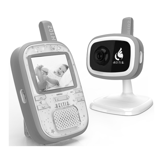
Thanks for purchasing Hestia H102 wireless monitoring system. Please make sure you have the following components in the packing. Monitor unit with flip stand Camera unit with camera stand For combo kit, one more camera unit is bundled with H102 wireless monitor system. - Page 7 Multi-purpose Mount Rechargeable battery AC adapters x2 Screw and User Manual double-sided tape A/C Adapter Information Chou Sen Electronics Manufacturer Kuantech Company Ltd. (Shenzhen) Co., Ltd. CS6D050100F series KSAS0050500100 series Model number 100-240V ~ 50/60Hz Input 1 0 0 - 2 4 0 V ~ 5 0 / 6 0 H z Output 5V 1A 5V 1A...
-
Page 8: Product Features And Overview
Product Features and Overview 3.1 Features and Specifications Digital 2.4GHz (FHSS) Wireless Transmission. Ÿ Extended transmission distance for greater than 300m in open area. Ÿ Automatic night vision capabilities for operating in dim environment. Ÿ Intercom (Push to talk) function allows dual way communication. Ÿ... -
Page 9: Overview
3.2 Overview Power ON/OFF Video off Button Antenna Power / Charging Indicator Sound Level Indicator TFT Display Brightness + / - B utton Menu / Button Microphone Speaker Volume / Button DC Jack Strap Holder Push to talk (PPT) Button Flip Stand Battery Door Monitor Unit... -
Page 10: Getting Started
Getting Started 4.1 Powering and battery charging Monitor Unit As shown in pic. 1, remove the silicon sleeve and flip stand from monitor unit. Then open the battery door. pic.1 Insert the rechargeable battery to the battery bay and plug into the battery socket as instructed in pic. -
Page 11: Powering Camera Unit
4.2 Powering Camera Unit Plug the A/C adapter into the wall electrical outlet. Then attach the cord to the DC Jack as shown in pic. 4. pic.4 4.3 Mounting Camera unit The camera unit was designed to s u p p o r t d i f f e r e n t m o u n t i n g mechanism, from simply putting on a table to mounting on a wall by screw or double-sided tape. - Page 12 Mount the camera unit by double-sided tape pic.6 1. Clean the mounting surface by alcohol. 2. Remove the cover label from the double-sided tape, and stick it onto the recess area of camera base plate, as s hown in pic. 6 Black Word 3.
-
Page 13: Back Mount Mechanism
Power cord cable can be inserted to the cable mounted as shown in pic. 8. 4.4 Back Mount Mechanism Both monitor and camera unit carried an identical back mount mechanism. Different accessories (flip stand, multi-purpose mount, camera stand) can be installed to either monitor unit or camera unit based on different needs. -
Page 14: Operation
Operation 5.1 General Operation User operation is divided into 2 different modes. General operation is referring to user operations when the capturing image being displayed on screen. 5.1.1 Power ON/OFF To power on Monitor unit, press the power button and hold for 1 second. -
Page 15: Icons Definition
5.1.2 Icons Definition Signal Reception Battery Capacity Camera number Volume / Brightness Level Camera Number Indicates the current camera shown on screen. The camera number will be displayed at numeric form inside the icon. Signal Reception Indicates the current signal reception strength from camera unit. -
Page 16: Operation
5.1.5 Switching Camera number Hot-keys is available for switching different camera number at general operation. Press and hold menu button, then press + button will switch to next camera number. Press and hold the menu button, then press - button will switch to previous camera number. Switching camera function is also available at menu mode, as Tips mentioned in section 5.5.1... -
Page 17: Menu Mode
5.2 Menu Mode Menu mode can be activated by pressing either menu button or menu once. The below screen will be displayed during menu mode. Title Function / Options Description Title Video Settings Audio Settings Camera Settings Load Defaults 4 main titles are available - Video, Audio, Camera and Defaults. -
Page 18: Menu Mode - Video
5.3 Menu Mode - Video 5.3.1 Saturation High saturated image Vivid Adjust the color saturation of Saturation Normal Normal saturation displayed images Low saturated image Cool 5.3.2 Night Vision Set ON the Night Vision mode Set OFF the Night Vision mode Select different Night Vision Use build-in light sensor to... -
Page 19: Menu Mode - Audio
5.4 Menu Mode - Audio 5.4.1 VOX Delay VOX is a power saving feature to turn off video and audio system of monitor unit, when the environment of camera side is silent. The system will be resumed automatically when camera unit detect noise. There are two user settings available for VOX function. -
Page 20: Auto Mute
5.4.4 Sound Level Indicator Sound Level indicator is the 4 indicators located at top of display screen, showing the sound level captured from camera unit. Set ON to activate this function, set OFF to disable the indicators. 5.4.5 Auto Mute Auto Mute function acts as a white noise eliminator, which shut down the audio system when no sound is captured from camera unit for 10 seconds. -
Page 21: Camera Pairing
5.5.2 Camera Pairing To pair a new camera unit, select a 'Not paired' camera number from Camera menu, and press 'OK'. Below screen will be shown : Select 'Pair' function and press 'OK' button. The monitor unit will start searching the camera unit and a 'Connecting' status will be displayed. -
Page 22: Auto Scan Mode
5.5.4 Auto Scan Mode Auto scan mode is an automatic camera switching function to all paired camera units at an interval of 15 seconds. The display sequence is at numeric order of camera number. For example : Cam1, Cam3 and Cam4 are paired, the sequence will be cam1 >... -
Page 23: Menu Mode - Load Default
5.6 Menu Mode - Load Default Select 'Restore factory settings…' function, and press 'OK' button. System will prompt to reconfirm the action, select 'YES' and press 'OK' button will restore the factory default. Select 'NO' and press 'OK' button will go back to Load Default page. Camera pairing information will not be deleted during factory Tips Tips... -
Page 24: Troubleshooting And Tips
Troubleshooting and Tips Q. I don't get a screen at all. Make sure both monitor and camera unit are turned on. The blue power LED will light up and indicate the system is powered on. If blue power LED is not light up, please check if the A/C adapter is properly connected to the devices and to the wall outlet. - Page 25 Tips: User can turn off the 'Out-of-range' audio alert manually Tips Tips as mentioned in section 5.4.3, if necessary. Q. Why I get a black and white image instead of color image? It is the night vision mode image generated by infra-red light. At default setting, the system will automatically detect the ambient light level, and trigger On/Off the night vision mode.
-
Page 26: Warranty Information
No other warranties are given. Declaration of Conformity : Hereby Hull Base International, declares that the H102 and the series is in compliance with essential requirements and other relevant provision of Directive 1999/5/EC.The product had designed, tested and manufactured according the European R&TTE... -
Page 27: Fcc Statement
FCC Statement WARNING: Modifications not authorized by the manufacturer may void users authority to operate this device. This device complies with part 15 of the FCC Rules. Operation is subject to the following two conditions: (1) This device may not cause harmful interference, and (2) this device must accept any interference received, including interference that may cause undesired operation. - Page 28 Copyright© of Hull Base International Ltd. All Rights Reserved www.hullbase.com...
Need help?
Do you have a question about the H102 and is the answer not in the manual?
Questions and answers