Advertisement
Quick Links
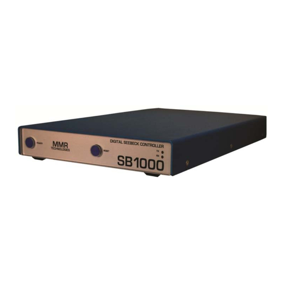
SB1000 Digital Seebeck Effect Controller
Installation & Operators Guide
Rev E ‐ July 2014
This document outlines the installation and setup of the MMR SB1000 Digital Seebeck Controller.
P a g e
| 1
41 Daggett Drive, San Jose, CA 95134
Phone: +1 (650) 962 9620
Fax: +1 (650) 962-9647 Email: info@mmr-tech.com
Web: www.mmr‐tech.com
Advertisement

Summary of Contents for MMR SB1000
- Page 1 SB1000 Digital Seebeck Effect Controller Installation & Operators Guide Rev E ‐ July 2014 This document outlines the installation and setup of the MMR SB1000 Digital Seebeck Controller. P a g e | 1 41 Daggett Drive, San Jose, CA 95134 Phone: +1 (650) 962 9620 Fax: +1 (650) 962-9647 Email: info@mmr-tech.com Web: www.mmr‐tech.com ...
- Page 2 23 P a g e | 2 41 Daggett Drive, San Jose, CA 95134 Phone: +1 (650) 962 9620 Fax: +1 (650) 962-9647 Email: info@mmr-tech.com Web: www.mmr‐tech.com ...
- Page 3 About the SB1000 Digital Seebeck Controller Specifications The SB1000 Seebeck Effect controller is built on and intended to replace the proven SB100 Seebeck Controller previously offered by MMR Technologies. See Page 9 for the Theory of Operation. This device provides accurate Thermo Electric voltage readings from an MMR Seebeck Stage and Refrigerator assembly. These devices are intended for use with MMR Refrigerators only. Voltage: 115VAC ‐ 220VAC 50/60Hz (Dual Voltage) ...
- Page 4 1x MMR 4‐Wire Kelvin Connection Breakout Board 1x SB1000 ‐ K2000 Link Cable Please connect the SB1000 as shown below. Do not connect both the RS232 Serial cable and USB cable simultaneously, these are provided as an option should you be short of spare PC ports. Once connected and with the PC Running, you may now power up the SB1000 device. Please first ensure the AC Power switch at the rear of the unit is 'ON' (see page 6 for further information). Press the front button labeled ...
- Page 5 5/. Select a Comm Port between 1 ‐ 16 that is not in‐use by other hardware. Click OK. (Note: On some computers you may need to disconnect (unplug) and reconnect the device to make the changes permanent) P a g e | 5 41 Daggett Drive, San Jose, CA 95134 Phone: +1 (650) 962 9620 Fax: +1 (650) 962-9647 Email: info@mmr-tech.com Web: www.mmr‐tech.com ...
- Page 6 Hardware Installation Front / Rear Panel Interface Note: The Power button must be held for 3 seconds to power down the unit. *Replace fuse with 3.15A Slow Blow (IEC 127‐2 or similar) ONLY. P a g e | 6 41 Daggett Drive, San Jose, CA 95134 Phone: +1 (650) 962 9620 Fax: +1 (650) 962-9647 Email: info@mmr-tech.com Web: www.mmr‐tech.com ...
- Page 7 Hardware Installation Getting Started Step 1 ‐ Device ports are easily verified through the welcome screen above. Select the port number the SB1000 Seebeck Controller is connected to (shown as present next to the SB1000) and press 'Poll'. If the SB1000 is connected to that port and powered on, it will respond with a Device name and Version number. If the port number is not visible try refreshing the port list by clicking the refresh icon above the "Poll'' buttons. If this does not resolve the issue try restarting the computer. For further assistance contact your system administrator and finally, the MMR Helpdesk (See contact information on Page 27). Step 2‐ Select 'Seebeck Experiment.' This will load the Seebeck experiment module. If there is no K2000 present, deselect "K2000' under hardware. This will disable temperature control for all Seebeck experiments. Errors will ...
- Page 8 SB1000 Spooler [Main Suite ‐> SB1000 ‐ > Show Spooler] This window shows the communications queue and response from the associated device; in this case the SB1000 Seebeck Controller. Troubleshooting is the primary use for this window. However clicking "Send" is a short cut to the ‘Main Communications Console' outlined in the Software Installation Guide. P a g e | 8 ...
- Page 9 MMR Programmable Seebeck Controller SB1000. The Seebeck stage is attached to the cold stage of an MMR refrigerator, which provides a given stable temperature for the measurement. The MMR Cold stage is controlled by the MMR K20000 Digital Temperature Controller. The Seebeck Stage has two outputs: V 1 and V2, which are monitored by a computer through the SB1000. The principle of operation is the following: assume that all four thermocouples are at the same ...
- Page 10 ) ‐ V2(P )} 1 = 2 (8) does not include ΔV 1 and ΔV2. The offsets have been removed. Certain hardware and software precautions have also been implemented to eliminate any possible electrical coupling between the heater and measurement circuits as well. P a g e | 10 41 Daggett Drive, San Jose, CA 95134 Phone: +1 (650) 962 9620 Fax: +1 (650) 962-9647 Email: info@mmr-tech.com Web: www.mmr‐tech.com ...
- Page 11 Definitions. In the following, various terms used in this Manual and in the operation of the System are defined. 1. Measurement point. The set temperature for the Seebeck stage provided by the MMR Cold Stage. Different measurement points are used in order to study the temperature dependence of the specific thermo‐voltage. 2. Experiment. The process that includes a sequence of measurement points; starting from the ...
- Page 12 27, or 128 readings. MMR Recommends a setting of '2' for most experiments. P a g e | 12 41 Daggett Drive, San Jose, CA 95134 Phone: +1 (650) 962 9620 Fax: +1 (650) 962-9647 Email: info@mmr-tech.com Web: www.mmr‐tech.com ...
- Page 13 If you are going to use the system at temperatures below ambient, you should also install all system components required for cooling according to the MMR Refrigerators Manual. P a g e | 13 41 Daggett Drive, San Jose, CA 95134 Phone: +1 (650) 962 9620 Fax: +1 (650) 962-9647 Email: info@mmr-tech.com Web: www.mmr‐tech.com ...
- Page 14 Notice: Be very careful while mounting the samples. Bad electrical or thermal contacts, asymmetrical location of the working junctions, and surface contamination can cause serious measurement errors. P a g e | 14 41 Daggett Drive, San Jose, CA 95134 Phone: +1 (650) 962 9620 Fax: +1 (650) 962-9647 Email: info@mmr-tech.com Web: www.mmr‐tech.com ...
- Page 15 Note: Impedance and Gain settings are indicated on the Amplifier board inside the chamber. The correct settings must be used or erroneous data will result. Click 'OK' P a g e | 15 41 Daggett Drive, San Jose, CA 95134 Phone: +1 (650) 962 9620 Fax: +1 (650) 962-9647 Email: info@mmr-tech.com Web: www.mmr‐tech.com ...
- Page 16 If a K2000 Temperature Controller is present, the temperature plot will automatically begin recording temperature data. P a g e | 16 41 Daggett Drive, San Jose, CA 95134 Phone: +1 (650) 962 9620 Fax: +1 (650) 962-9647 Email: info@mmr-tech.com Web: www.mmr‐tech.com ...
- Page 17 The above plot shows the Temperature Control during the Seebeck Experiment. This data can be printed from within the K2000 Temperature Graph Window if needed. P a g e | 17 41 Daggett Drive, San Jose, CA 95134 Phone: +1 (650) 962 9620 Fax: +1 (650) 962-9647 Email: info@mmr-tech.com Web: www.mmr‐tech.com ...
- Page 18 Deviation is also present along with the Percentage Change and Min Max Values. If no temperature control is present only 1 point will be plotted. P a g e | 18 41 Daggett Drive, San Jose, CA 95134 Phone: +1 (650) 962 9620 Fax: +1 (650) 962-9647 Email: info@mmr-tech.com Web: www.mmr‐tech.com ...
- Page 19 Note: Sending command SMx starts constant measurement at desired average rate. Communications & Byte Order Command Example: 'SM2' (starts measurement at 2^2 = 4 readings per average) 1/. Set RTS High 2/. Wait for CTS 3/. Send 'S' as a Character (VB Example on Next Page) 4/. Send 'M' as a Character (VB Example on Next Page) 5/. Send Average as a 2‐Byte Word (Highbyte First, Lowbyte Second) 6/. Set RTS Low P a g e | 19 41 Daggett Drive, San Jose, CA 95134 Phone: +1 (650) 962 9620 Fax: +1 (650) 962-9647 Email: info@mmr-tech.com Web: www.mmr‐tech.com ...
- Page 20 Exit Function End If Wend MSComm1.OutBufferCount = 0 MSComm1.InBufferCount = 0 'Clear Buffers MSComm1.Output = Chr$(S) + Chr$(M) + Chr$(val / 256) + Chr$(val Mod 256) MSComm1.RTSEnable = False End Function P a g e | 20 41 Daggett Drive, San Jose, CA 95134 Phone: +1 (650) 962 9620 Fax: +1 (650) 962-9647 Email: info@mmr-tech.com Web: www.mmr‐tech.com ...
- Page 21 For all other errors or issues please contact the MMR Help Desk (see Page 22) P a g e | 21 41 Daggett Drive, San Jose, CA 95134 Phone: +1 (650) 962 9620 Fax: +1 (650) 962-9647 Email: info@mmr-tech.com Web: www.mmr‐tech.com ...
- Page 22 Troubleshooting Help Desk and MMR Contact Information Help Desk Email Address: support@mmr‐tech.com Bug Reporting: spdbugs@mmr‐tech.com Technical Support Email Address: matt@mmr‐tech.com Sales & Marketing Department: sales@mmr‐tech.com Help Desk: +1 650 962 9620 Office Hours: 7:30am ‐ 5:00pm (Pacific Time) Monday ‐ Friday Physical Address: 41 Daggett Drive, San Jose, California 95134 ...
- Page 23 Electrical equipment for measurement, control, and laboratory use Pressure Equipment Directive (97/23/EC) Conformity is declared to Annex I Essential Requirements of the Directive Application of Council Directives: Electromagnetic Compatibility Directive (EMC) 2004/108/EC Conformity is declared to Annex I and II (EMC) 2004/108/EC P a g e | 23 41 Daggett Drive, San Jose, CA 95134 Phone: +1 (650) 962 9620 Fax: +1 (650) 962-9647 Email: info@mmr-tech.com Web: www.mmr‐tech.com ...
Need help?
Do you have a question about the SB1000 and is the answer not in the manual?
Questions and answers