
Summary of Contents for UGMO ProHome PH100WS
- Page 1 Installation and User Manual UgMO Technologies• 840 First, Suite 300 • King of Prussia, PA 19406 • www.UgMO.com Please leave with property owner...
- Page 2 Installation and User Manual...
- Page 3 600 feet, depending on soil type, depth, or driest conditions expected. UgMO limits watering to and line of site to the Base Station. UgMO is easy to in- be ‘just enough’. stall, effective and long lasting. It is not uncommon for a...
- Page 4 Table of Contents I N STA L L AT I O N A N D U S E R M A N UA L Components ..............................2 Preparing to Install ............................4 Site Assessment ............................... 5 Installing the Base Station ..........................6 Mounting the Base Station ........................
- Page 5 Activating the Archives ....................... 29 Installing Sensors ............................30 Placement of Sensors.......................... 32 Completing the Installation ......................... 34 Appendix A: Troubleshooting Guide ......................36 Appendix B: Soil Property Field Test ......................38 Appendix C: Watering Guidelines: Setting the Irrigation Controller for UgMO .......... 44...
-
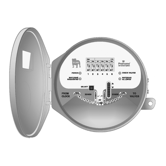
Page 6: Components
“Wiring Harness”: 18 conductor cable and strain relief leading to irrigation clock Selection wheel 10. Lit when UgMO is allowing watering and zone valve is open 11. Check valve light illuminates when UgMO identifies a wir- ing short in existing irrigation system... -
Page 8: Preparing To Install
1.25 inch Putty Knife: Or something similar for cutting slot in soil for tine insertion. 10 Inch Crescent Wrench or Channel Locks: To tighten strain relief nut. Tape Measure: To measure sensor location. UgMO Soil Press: To determine soil type. Irrigation Flags: To mark sensor locations. Yellow Whisker Marker... -
Page 9: Site Assessment
Site Assessment Site Survey Visually inspect the property, location of clock and placement of the Base Station. Run all valve stations to: • Confirm zone location and sprinkler count per zone. • Identify areas within each zone to place sensors (rule of thumb is to place the sensors between irrigation sprinklers, in an area that tends to be the driest and where you have the best line of sight to the Base Station with the least obstructions. -
Page 10: Installing The Base Station
Installing the Base Station MOUNTING THE BASE STATION Choose the location of the UgMO Base Station following these guide lines: • Base Station needs to be 12-18 inches away from and higher than the irrigation clock. • Base Station should be within 600 feet of any possible sensor location. -
Page 11: Wiring A Single Base Station
WIRING A SINGLE BASE STATION IMPORTANT NOTE: Determine if the irrigation system uses a pump or Master Valve. Look at the irrigation wiring, if there is a wire attached to a terminal labeled “P/MV” or “Pump/Master Valve”, the system has one of these present. IMPORTANT NOTE: DO NOT ATTACH THE POWER CONDUCTORS UNTIL ALL OTHER WIRES HAVE BEEN ATTACHED Using wire labels, label all valve stations,... - Page 12 Installing the Base Station WIRING A SINGLE BASE STATION (CONTINUED) Remove the wire (in the irrigation clock) from the Valve Station #2 terminal and butt WHITE connect it to the wire with a STRIPE V2/V8 labeled and crimp it so its attached securely.
- Page 13 11. Remove the Pump Master wire from the terminal labeled “P/MV” or “Pump Master” and butt connect GRAY P/M (V) it to the wire labeled , from the “Valve Bundle”, and crimp it so it’s attached securely. BROWN P/M (C) 12.
-
Page 14: Determining Ac Polarity Of Existing Irrigation Clock
Installing the Base Station DETERMINING AC POLARITY OF EXISTING IRRIGATION CLOCK BLACK Open the wiring compart- Attach the wire IMPORTANT NOTE: ment of the irrigation clock. from the wiring harness “Power Bundle” to the The correct polarity of the AC connection is critical: Set the Voltmeter to “AC (AC -) terminal. -
Page 15: Wiring 2 Base Stations With A Pump/Master Valve To Control Up To 12 Stations
WIRING 2 BASE STATIONS WITH A PUMP/MASTER VALVE TO CONTROL UP TO 12 STATIONS Drill two one inch (1”) holes BLUE STRIPE labeled IMPORTANT NOTE: in the irrigation controller , from the wiring harness Determine if the irrigation system uses a pump or master to allow easy insertion of “Valve Bundle”, and crimp it valve. - Page 16 Installing the Base Station WIRING 2 BASE STATIONS WITH A PUMP/MASTER VALVE TO CONTROL UP TO 12 STATIONS (CONTINUED) PINK C2/C8 Identify the wire labeled from the “Clock Bundle” and attached that wire in the irrigation clock’s Valve Station #2 terminal where you removed the wire in step 5 above.
- Page 17 10. Remove the Pump Master wire from the terminal (in the irrigation clock) labeled “P/MV” or “Pump Master” and butt connect it to the GRAY P/MV (V) wire labeled , from the “Valve Bundle” coming from Base Station #2 (controlling valve stations 7-12). BROWN P/MV (C) 11.
-
Page 18: Base Station User Interface
Base Station User Interface MAIN SCREEN 1. On power-up, you’ll see the Introduction Screen. This times out after 10 seconds, or press the Select Button (#4 on page 2) to display the Main Screen. 2. The Main Screen is divided into six main sections identified as A - F on the figure to the right. -
Page 19: Auto/Bypass Indicator
If the irrigation system has a Pump or Master Valve, this symbol will flash to indicate that the Pump or Master Valve is operating when a zone is turned on. This area flashes “ON” whenever UgMO allows a zone to come on regardless of the presence of a Pump or Master Valve. -
Page 20: Zone Moisture Level Indicator
When a zone flashes “OFF”, this indicates that the irrigation Indicates that the present moisture level for this zone is clock is requesting water but UgMO is not allowing it. within the programed UgMO moisture levels and only the amount of watering required to remain at this moisture level will be allowed. -
Page 21: Battery And Wireless Strength Indicator
Battery and Wireless Strength Indicator The bottom row of each column displays the wireless connection and battery strength of each sensor. This indicates that the zone has not been paired to a sensor. All columns will display these “dashes” when the Base Sta- tion is first powered on and no sensors have been paired. -
Page 22: Manage Sensors
Base Station User Interface MANAGE SENSORS Wireless Sensors need to be linked (paired) to a Base Station and then assigned to one or more irrigation zones. This is an easy process. Pairing sensors to Base Station: Choosing Sensors Read the Network Address (NWA) on the Tine Sleeve or bottom of the wireless sensor. This will be the 8 digit numbers and/or letters following “NWA”... - Page 23 IMPORTANT NOTE: THE WIRELESS SENSOR TINE SLEEVE The tine sleeve acts as an “ON/OFF” switch when placed on the sensor. Removing it activates the sensor or turns it on. Every time the sensor is turned off and back on, the sensor goes into a rapid transmission mode. It transmit 10 times at 10 second intervals to support pairing.
-
Page 24: Assigning A Common Sensor
Base Station User Interface MANAGE SENSORS (CONTINUED) Assigning A Common Sensor The system supports the concept of a “Common Sensor” which is designed to ensure the system operates properly even when the wireless signal from a distant sensor is lost. This can be due to a dead battery, temporary interference or reduced range due to heavy rain. With a common sensor assigned, the system will use the data from the Common sensor in the system as a fail-safe until connectivity to the lost sensor is regained. -
Page 25: Assigning A Sensor To More Than One Zone
Assigning a sensor to more than one zone It is possible to assign a Sensor to more than one zone so that both zones are managed by the data from that sensor. This is usually done when two zones are very similar in the amount of sun or shade they are exposed to. Assigning more than one sensor to one zone It is also possible to assign more than one Sensor to a single zone. -
Page 26: Pairing Sensors To Base Station: Manual Entry
(CONTINUED) UgMO allows you to manually pair sensors to a base station. This is particularly helpful if a sensor is already buried in the ground and you are not able to replace the tine sleeve to set it to rapid broadcast. -
Page 27: Setting Moisture Levels
MANAGING SYSTEM SETTINGS Setting Global Auto and Bypass When the system is set to “Auto”, UgMO controls the zone watering. When set to “Bypass” in this screen, UgMO will not control ANY zones. This setting is useful when testing the irrigation clock in manual mode. -
Page 28: Setting Global Cold Temperature Override
Base Station User Interface MANAGING SYSTEM SETTINGS (CONTINUED) Setting Global Cold Temperature Override The Cold Temperature Override is set globally and will not allow watering when the soil temperature reaches a preset value regardless of the moisture readings in the soil. From the Main Screen rotate the wheel up one click to the [Manage System Settings] page and press the [Select] button. -
Page 29: Manage Zone Settings
MANAGE ZONE SETTINGS Zone Bypass Settings There are times when you may need to bypass UgMO for a specific zone but not all of the zones (e.g. establishing new plantings). At other times, you may wish to restrict a zone from watering (e.g. -
Page 30: Multiple Sensors Per Zone Settings
(CONTINUED) Multiple Sensors per Zone Settings It is possible to assign more than one sensor to a zone. (See Manage Sensors). UgMO allows you to determine how the sensor data is used by the system to manage the watering. The system default setting is set to average the data coming from all the sensors in the zone. -
Page 31: View Sensors
VIEW SENSORS Determining Wireless Signal Strength From the Main Screen move the [Selection Wheel] up three clicks until you see [View Sensors] highlighted under Menu and push [Select]. Each screen displays the signal quality, temperature and wetness level of an individual sensor. -
Page 32: Reading The View Sensor Screen
Base Station User Interface VIEW SENSORS (CONTINUED) Reading the View Sensor Screen Short-Term Signal Quality R Rating: If there are gaps or the columns This value represents Indicator: vary in height, transmissions R-RATING At the bottom of the the % of expected transmissions have been missed. -
Page 33: Activating The Archives
Activating the Archives The Base Station is capable of recording a detailed history of watering events. This is called an Archive. This is an advanced feature used to diagnose system issues and not suggested for normal operation. From the Main Screen turn the [Selection Wheel] up one click to the [Manage System Set- tings] page and press [Select] . -
Page 34: Installing Sensors
Installing Sensors PLACEMENT OF SENSORS Placement of Sensors Place the sensors on top of the ground in the corresponding Go back to the zone one sensor. Dig a hole using a small shovel zones that they represent on the Base Station and remove the or a hole cutter approximately one and quarter times the length tine sleeves. - Page 35 IMPORTANT NOTE: SENSOR NOT CONNECTING If any sensors are not communicating (“XX” on the main screen is not being replaced by a full “antenna”) after 12 minutes, refer to the trouble shooting guide for solutions.
-
Page 36: Placement Of Sensors
Installing Sensors PLACEMENT OF SENSORS (CONTINUED) Placement of Sensors Using a 1.5” putty knife or something similar, create a vertical slit Place the whisker, loop side down so that the top is out of the in the soil, so the center of the slit is 1.5” to 1.75” below the top of ground at a level that is close to the length of the grass or where the soil and within the root zone of the plant. - Page 37 Bury the sensor and whisker, making sure to pack the soil firmly as you fill the hole and place the turf cap back on. Repeat steps 6-9 for all sensors. Repeat the field soil test only if you are dealing with different types of soils for the different zones (flower beds, turf areas, mounds, valleys, etc.) Once all sensors are buried return to the Base Station and restart it.
-
Page 38: Completing The Installation
are communicating (use [View Sensors] page to do this). UgMO may not allow watering. (See page 15). On the front face of the Base Station the “Watering Requested” and “Watering Al- Make sure that the Base Station is set to “Auto”. - Page 39 ProHome Sensor Location reference Guide Zone/nWA reference 1 Measurement reference 2 Measurement...
-
Page 40: Appendix A: Troubleshooting Guide
3) Sensor is buried too deep or ground is heavily saturated. Cannot run a zone from the 1) UgMO is not allowing watering 1) If the zone reads WET on the Main Screen, place Base Station into irrigation clock after Base because the zone is reading WET. - Page 41 3) Inspect shape and condition of valve diaphragm. Lawn or Landscape looks Dry 1) UgMO Wetness Threshold Level is set If the lawn appears to be too dry, check the UgMO screen to see the too low. present moisture conditions.
-
Page 42: Appendix B: Soil Property Field Test
While there are 12 types of soil with endless variations found in the field, we can narrow this to 4 types for installation purposes: Type 1: Sand with an initial UgMO setting of 3 Type 2: Silty Loam with an initial UgMO setting of 5 Type 3: Clay with an initial UgMO setting of 7... - Page 43 The process includes a few steps as follows using the soil tester illustrated below: Step 1: Take a handful of soil from the depth where the sensor will be placed and fill the inside cup of the soil tester. Be sure that the soil is firmly placed in the cup by pressing on it with your palm.
- Page 44 Appendix B: Soil Property Field Test Step 2: Saturate the soil with water slowly so that the water absorbs through the entire soil sample. This takes about a minute for most soils. It is important that the soil is saturated before continuing to step 3:...
- Page 45 Step 3: Squeeze the soil tester shut as firmly as possible to force soil and water to the holes at the bottom of the tool. The reaction of the soil at the holes is what will determine the soil type for installation and threshold setting purposes:...
- Page 46 Appendix B: Soil Property Field Test Step 4: Determine the reaction of the soil and water at the holes on the bottom side of the tool. Use the scale to determine what soil type and setting should be used: Type 1: Type 2: Indicated by semi-clear water exiting the holes.
- Page 47 Type 4: Indicated by very dark muck-like water from Type 3: Indicated by formed soil extensions exiting the organic deposits in soil. Some very fine non-gritty holes. Initial setting = 7 Initial setting = 9 material may squeeze.
- Page 48 For example, if a zone is typically set extension of time only prolongs the availability of water due to to run for 60 minutes during August. UgMO will ensure that the longer duration of water input. Whether the water stops the zone is not overwatered during other times of the year.
-
Page 50: Customer Service
Customer Service: Please visit UgMO.com or call 877-500-UgMO for customer service. This product should not be used for anything other than what is described in this document. This product should only be serviced by trained and authorized personnel. FCC Notice: This device complies with Part 15 of the FCC Rules. Operation is subject to the following two conditions: (1) This device may not cause harmful interference, and (2) This device must accept any interference received, including interference that may cause undesired operation.
Need help?
Do you have a question about the ProHome PH100WS and is the answer not in the manual?
Questions and answers