
Subscribe to Our Youtube Channel
Related Manuals for Atlas Copco ACTA 4000


Summary of Contents for Atlas Copco ACTA 4000
- Page 1 User Guide ACTA 4000 Also valid for ACTA 3000 Atlas Copco Tools and Assembly Systems 9836 4171 01 2008-12...
- Page 2 Copyright Atlas Copco Tools and Assembly Systems Note! This manual can be altered without further notice. For further information log in to Atlas Copco www.atlascopco.com...
- Page 3 ACTA 4000 User Guide Contents Contents Contents ......................... 3 System overview ....................7 ACTA functionality ........................7 1.1.1 ACTA Basic..........................8 1.1.2 ACTA Quality Control......................8 1.1.3 ACTA Advanced Analysis ...................... 8 ToolsTalk QAT ..........................8 How to use this guide........................9 1.3.1 Revision History ........................10 Interface .......................11...
- Page 4 Contents ACTA 4000 User Guide 4.6.2 Select Tool ..........................54 4.6.3 Delete Tool ...........................55 4.6.4 Clear all measurements ......................55 4.6.5 Backup tool ...........................55 4.6.6 Information ..........................56 Program (Prog.) ........................57 4.7.1 Application Data Setup ......................57 4.7.2 Tooltype setup ........................58 4.7.3 Measurement setup ......................59 4.7.4...
- Page 5 Control charts example ...................... 115 9.2.2 X-bar and Range coefficients table ..................120 Capability studies........................121 ISO 5393 calculations ......................122 Technical specifications................... 123 10.1 Back panel connectors, ACTA 4000..................123 10.1.1 Transducer Pin Description ....................123 10.1.2 Barcode Reader ......................... 124 10.2 Default Setups........................125 10.2.1...
-
Page 7: System Overview
Introducing ACTA, combining tightening analysis functionality with integrated tools management and statistic process control (SPC). This user guide describes the ACTA 4000 and ACTA 3000, revision 3.x functionality. When referring to ACTA only, the functionality is valid for both versions. Other versions of ACTA are not covered in this user guide. -
Page 8: Acta Basic
Advanced Analysis is the most advanced version for graphical analysis of the tightening characteristics of various tools or joints. In addition to the Basic and Quality Control features, the following is included: Tightening traces with zoom-in Print traces, for ACTA 4000 through ToolsTalk QAT Trace transfer to ToolsTalk QAT ToolsTalk QAT... -
Page 9: How To Use This Guide
ACTA 4000 User Guide System overview keep a record of work in progress. ToolsTalk QAT can even keep track and remind you of maintenance and service intervals. Use ACTA with ToolsTalk QAT software to have a complete quality management tool at your service or your complete ISO 9000 under one icon in your PC. -
Page 10: Revision History
System overview ACTA 4000 User Guide Tool calibration If the tool needs adjustment, this is normally done through the ACTA calibration procedure where the tool software is updated. A calibration can also be done manually (screw adjustment on tool). The tool calibration can be done with or without a synchronized controller. For instructions, see section Calibrating tools and equipment. -
Page 11: Interface
8 SHIFT 9 Numeric keypad 10-12 Function buttons 10-12 The front panel layout is the same for all versions of ACTA 4000 or ACTA 3000. Apart from the display, it features LED indicators, soft keys and an alpha-numeric keypad. Name Description... -
Page 12: Display
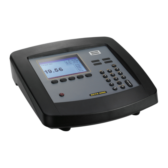
Display ACTA features a large back-lit 72 x 96 mm display with a dialog box-like interface to allow accurate measurement readings and simple usage. ACTA 4000 has a color display, ACTA 3000 has a black and white display. ACTA also features a power-save function that deactivates the back-lighting on the display if it is not used for 30 seconds. -
Page 13: Menu Blocks
ACTA 4000 User Guide Interface Result header with battery status, communication symbol, tool or application name, and number of tightenings (in batch) Measurement dialog box with torque and angle results, statistical results and last five tightenings. This figure shows the basic view... -
Page 14: Input Dialog Boxes
Interface ACTA 4000 User Guide 2.1.4 Input dialog boxes An input dialog box appears if the option you have selected requires specific parameters to be set. Opening data boxes To access the data boxes, do one of the following: Highlight it by... - Page 15 ACTA 4000 User Guide Interface When all data in the dialog box is correctly filled in, do one of the following: Highlight on the display and press to confirm and exit the dialog box ENTER Press on the numeric keypad to confirm and exit the dialog box...
-
Page 17: Getting Started
Calibration certificate USB cable CD with ACTA software, ToolsTalk QAT software, and ACTA 4000 Printer Service The calibration certificate must be stored in a safe place. To access the functionality described in this user guide when using an ACTA 3000, an upgrade package is required. -
Page 18: Installing Software
Getting started ACTA 4000 User Guide 3.2.1 Installing software To install the software from the CD, do the following: 1. Insert the CD into your PC. 2. Install the Printer Service and ToolsTalk QAT. Printer Service is free of charge and ToolsTalk QAT is possible to use for 60 days without a license. -
Page 19: Startup
ACTA is Calibration communicating with the Atlas Copco torque transducer and performing an automatic setup. It reads the transducer’s serial number and calibration data, which it stores in its memory. ACTA can work with most major transducer types. If you use an Atlas Copco non- memory transducer or a different brand, see section Technical specifications on how to set up your transducer before continuing. -
Page 20: Measuring Tools
Wrench Peak (DD) Static installed torque For more information about strategies, see section Measuring strategies. For more information about filter frequency, contact Atlas Copco. Do the tightening operations. The result is displayed in the dialog box after each tightening. Measurement Save and print the result. - Page 21 ACTA 4000 User Guide Getting started Select menu block Q.prog Select and press Synchronize ENTER Select controller. Select tool type and insert input target torque. 1 None For pulse tools, also insert filter frequency 2 Other controller For wrenches, select measurement strategy...
-
Page 22: Connecting Toolstalk Qat
Getting started ACTA 4000 User Guide Connecting ToolsTalk QAT To connect a computer with ToolsTalk QAT to ACTA, do the following: Connect ACTA and the computer with RS 232 cable or USB cable, or connect ACTA to the network with an Ethernet cable. -
Page 23: Programming Acta
ACTA 4000 User Guide Programming ACTA Programming ACTA This section shows the programming tree for ACTA Basic, Quality Control and Advanced Analysis, displaying the full functionality of each version. The section explains how to use the different functions and parameters of the programming tree to program your ACTA. - Page 24 Programming ACTA ACTA 4000 User Guide View Print Q.Prog Stat Basic Continuous Direct driven All tightening Custom Tool rundowns Pulse Statistics torque Trace Transducer info Wrench Statistics angle Tool setup Click wrench Statistics pulses History Tool statistics Synchronize Tool calibration...
-
Page 25: View
ACTA 4000 User Guide Programming ACTA Conf Datab Prog A.lyse Interface New tool Application data setup Zoom in User Select tool Tool type setup Zoom out User defined soft keys Delete tool Measure setup Adjust position Tightening Selected tool Ext measure setup... -
Page 26: Print Menu
ACTA 4000 To be able to print reports from ACTA 4000, ACTA 4000 Printer Service software must be installed on a PC and ACTA connected to it through the serial or the USB port. The report selected in ACTA is printed on the printer that is set up from the PC. - Page 27 ACTA 4000 User Guide Programming ACTA Print menu, ACTA 3000 and ACTA 4000 Print 1 Continuous 2 Tool rundowns 3 Transducer info 4 Tool setup 5 Tool statistics 6 Tool calibration 7 ISO 5393 8 Database 1 All tools rundown...
- Page 28 5 Database summary Prints a summary of all tools. 9 Trace Prints a trace of the last tightening operation. For ACTA 4000, ToolsTalk QAT must be used for printing traces. To terminate a printout in progress, press menu block Abort See section Port for print settings, and section Printouts from ACTA for examples of the printout reports.
-
Page 29: Quick Programming (Q.prog.)
ACTA 4000 User Guide Programming ACTA Quick Programming (Q.Prog.) For programming instructions, see section Using Quick programming. Q.Prog 1 Direct Driven 2 Pulse 3 Wrench 4 Click Wrench 5 Syncronize 1 None 1 Direct Driven 2 Pulse 3 Wrench 4 Click Wrench... -
Page 30: Quick Programming Tools
Used when checking installed torque in an already tightened joint. 4 Click wrench Used when checking the release torque on a click wrench. 2 Other controller Selected when a non-Atlas Copco controller is used. For tool type, see above. 3 Focus2000/PF2000 Type of controller. 1 Manual input Used if no connection is possible. -
Page 31: Iso 5393
ACTA 4000 User Guide Programming ACTA 5 PF3000/PF4000 Type of controller. 1 Manual input Used if no connection is possible. 2 RS232 Normally used for direct communication with controller 6 PowerMACS Type of controller. 1 Manual input Used if no connection is possible. - Page 32 Programming ACTA ACTA 4000 User Guide Performing ISO 5393 capability study Ensure that the test joints are set up and that the transducer and tool are connected. To view tool/Pset in the , open and set Result header Conf>Interface>User Show Pset Select menu block Q.prog...
- Page 33 ACTA 4000 User Guide Programming ACTA Viewing ISO 5393 calibration results The tightening and result of the ISO 5393 calibration is stored in the database within the four tools used. To see the result in ACTA (only torque and angle):...
-
Page 34: Statistics (Stat.)
Programming ACTA ACTA 4000 User Guide Statistics (Stat.) ACTA can save and provide torque, angle and number of pulses for each measured tightening operation performed with a tool. In addition to this, the QC and AA versions can calculate and supply detailed statistics of all the tightening operations saved in the database for each specific tool. -
Page 35: All Tightening
ACTA 4000 User Guide Programming ACTA 4.4.1 All tightening This window is actually a chain of three windows, displaying statistics on all tightening operations of the selected tool. Use the soft key arrows to navigate through your tightening statistics. The right/left arrows change statistical window as shown below. -
Page 36: Statistics Torque, Statistics Angle And Statistics Pulse
Programming ACTA ACTA 4000 User Guide 4.4.2 Statistics torque, Statistics angle and Statistics pulse These windows are also built up of a chain of windows. They display statistics on torque, angle or number of pulses depending on which was chosen in the pull-up menu. Each statistical parameter is calculated on all measured tightening operations saved during the measurement session for the specific tool. -
Page 37: History
ACTA 4000 User Guide Programming ACTA Window Menu item Description Subgroup statistics X-bar min. Minimum mean torque for subgroups. torque/angle/pulses X-bar max. Maximum torque/angle/no of pulses for subgroups. R min. Minimum torque/angle/no of pulses R (range) for subgroups. R max. - Page 38 Programming ACTA ACTA 4000 User Guide The shift-clear combination clears all tightening operations of the selected tool, while Datab>Clear all measurements clears all tightening operations of all tools. Each tool has its own history memory with space for the last five X, R and σ values. The history of torque, angle and no of pulses can be studied in four different windows as described below.
-
Page 39: Manual Input
ACTA 4000 User Guide Programming ACTA 4.4.4 Manual Input This function allows you to enter manual measurement values, including Torque, Angle and Pulses, in to your ACTA. This is useful where it may be difficult to access an application on the line with a transducer connected to ACTA. -
Page 40: Configuration (Conf.)
Programming ACTA ACTA 4000 User Guide Configuration (Conf.) In the configuration menu block, parameters customizing your ACTA to match your demands and requirements are set up. Conf 1 Interface 1 User 2 User defined soft keys 3 Tightening 4 Port 1) -
Page 41: Interface
ACTA 4000 User Guide Programming ACTA 4.5.1 Interface In the user interface dialog box, user specific interface options are set. The following parameters and alternatives exist. User The following items are available: Menu item Description 1 Backlight Allows you to select display backlight on or off. When the ACTA is running on battery power, the energy saving function is active. - Page 42 Programming ACTA ACTA 4000 User Guide Manual tight Stat > Manual input > Tightening Tool comment Stat > Manual input > Tool Comment Seq no. Stat > Manual input > Sequence number User Manually input User ID (4 characters) responsible for each tightening until next time user function is called.
- Page 43 ACTA 4000 User Guide Programming ACTA Tightening In the tightening interface dialog box, options regarding the tightening operations are set. 1 Default torque unit In Basic ACTA, this sets the units for the torque. Options: Nm, ozf.in, lbf.in, lbf.ft, kgf.m, kgf.cm, and Ncm.
- Page 44 Programming ACTA ACTA 4000 User Guide 8 New seq nr Sets ACTA to ask for a new sequence number. A new sequence number question may be asked automatically after a completed tightening operation. Whether or not this question is displayed depends on the parameter selected.
- Page 45 ACTA 4000 User Guide Programming ACTA About Routing The Routing function, set in the Tightening interface dialog box, causes ACTA to select the tool for the next tightening operation automatically. The flow of tools in the Tool Database list is managed by ToolsTalk QAT.
- Page 46 Programming ACTA ACTA 4000 User Guide Port (ACTA 3000 only) This is where you set your printer and communication preferences. 1 Printer protocol Here you select the protocol that suits your printer. ACTA 3000 can communicate with some of the printers on the market using one of the following protocols: Epson, IBM and PCL3.
-
Page 47: Calibration
From this pull-up menu calibrations are executed. The following calibrations are available: 1 ACTA Calibration of ACTA. See section Calibrating tools and equipment for details. Only authorized service personnel. Contact Atlas Copco. 2 Deadweight Calibration with deadweight equipment. See section Calibrating tools and equipment for details 3 Tool Calibration of tool. - Page 48 Then select in the menu to perform a Shunt calibration Conf.>Diagnostics new shunt calibration. If you are not using an Atlas Copco Tools IRTT transducer with memory, read the section below for setup instructions. 48 (136) 2008-12 9836 4171 01...
- Page 49 ACTA 4000 User Guide Programming ACTA Setting up your non-Atlas Copco memory type transducer By selecting in the menu or by connecting a new transducer, a Shunt calibration Conf>Diagnostics transducer database selection dialog box is displayed, see figure below. This dialog box consists of a list of 10 positions.
- Page 50 Programming ACTA ACTA 4000 User Guide ACTA 4000 dialog box Sensitivity List of torque sensors and their normal output. Name Bridge Add. Req. voltage sensitivity supply 0,59 mV/V 0,59 mV/V Bridge resistance 700 Ω 0,8 mV/V 0,8 mV/V Bridge resistance 700 Ω...
-
Page 51: Transducer Memory
The transducer memory information is shown in two dialog boxes. To change between the two dialog boxes use the right and left arrow soft keys. They are displaying the data received from an Atlas Copco memory transducer if such is connected to ACTA. -
Page 52: Communication
Contact your Atlas Copco service representative to recalibrate and reset the transducer. 4.5.5 Communication In this pull-up menu choice of communication is made. From here you can also control ACTA 4000 when performing automatic calibration. 1 Controller Sets up for communication with a controller. -
Page 53: Product Information
4.5.7 Options The options are customer specialized features that can be enabled in ACTA 4000. They are not described in this manual. For further information, please contact your Atlas Copco representative. 9836 4171 01 2008-12... -
Page 54: Database (Datab)
Programming ACTA ACTA 4000 User Guide Database (Datab) Under the menu block, the Quality Control and Advanced Analysis versions feature a tool database Datab where you can organize tools as well as measurement data for each tool. Datab 1 New tool... -
Page 55: Delete Tool
ACTA 4000 User Guide Programming ACTA 4.6.3 Delete Tool This lets you delete either the selected tool or all tools from the database. The tools are deleted along with their tightening. Make sure you select the tool up for deletion prior to performing delete selected tool. -
Page 56: Information
Programming ACTA ACTA 4000 User Guide In ToolsTalk QAT, the tightening are added to the existing tool. No separate back-up tool is created in ToolsTalk QAT. 4.6.6 Information This window displays information concerning the database. Menu item No. of tools in database No. -
Page 57: Program (Prog.)
ACTA 4000 User Guide Programming ACTA Program (Prog.) This is the menu block containing the programming tree for all measurement parameters and the statistical parameters for your database. The programming performed here can also be carried out using ToolsTalk QAT. See the ToolsTalk QAT manual for instructions. -
Page 58: Tooltype Setup
Programming ACTA ACTA 4000 User Guide 5 Target torque Specify the target torque. The target torque is used whenever the controller mode is set to ACTA. This is the case in Multistage measurement strategy or in Peak measurement strategy with ACTA as controller (see Available measuring strategies). -
Page 59: Measurement Setup
Used to select the type of communication based on tool type; for example PF, PowerMACS, air tool. See section Communication. Options: Manual input, RS232, Ethernet (ACTA 4000 only). When selecting Manual input, the user is asked for controller torque and controller angle in input fields after each tightening operation. -
Page 60: Ext. Measurement Setup
Programming ACTA ACTA 4000 User Guide strategy is found in section Measuring strategies . 4 Control Mode Select if the Controller or ACTA starts the tightening. Valid for PF or PowerMACS when communication is set to RS232 or Ethernet. See also section Communication. -
Page 61: Statistical Setup
ACTA 4000 User Guide Programming ACTA tightening result. Enter a numeric (ms) value. 7 End time The time ACTA waits after the Cycle Complete level before the tightening cycle is considered to have ended. This delay time is necessary for the two-stage strategy and for pulse tools. Enter a numeric (ms) value manually. - Page 62 Programming ACTA ACTA 4000 User Guide Group and Batch In this dialog parameters regarding subgroups and batches are set. For more information on batch result representation, see section Batch Result window. 1 Batch size This is where you define how many tightening are used when performing measurements with ACTA.
- Page 63 ACTA 4000 User Guide Programming ACTA 3 Torque LCLx Here is where you define the lower control limit for each subgroup x-bar value. 4 Torque UCLx Here is where you define the upper control limit for each subgroup x-bar value. See the Statistics chapter for more information.
- Page 64 Programming ACTA ACTA 4000 User Guide values. 7 Angle CM > Here is where you define the minimum allowed CM value. Values below this minimum value will initiate statistical alarms. 8 Angle CMK > Here is where you define the minimum allowed CMK value. Values below this minimum value will initiate statistical alarms.
-
Page 65: Display Setup
ACTA 4000 User Guide Programming ACTA values. 6 Result UCLr Here is where you define the upper control limit for each subgroup range values. 7 Result CM > Here is where you define the minimum allowed CM value. Values below this minimum value will initiate statistical alarms. - Page 66 Programming ACTA ACTA 4000 User Guide 2 Stat parameter 1 These parameters are displayed in the top right part of ACTA custom measurement display. They show real-time statistical calculations on your selection in Parameter 1. X, σ Mean and sigma for parameter...
-
Page 67: Analyse (A.lyse)
ACTA 4000 User Guide Programming ACTA If only one parameter is selected, two pairs of statistical parameters can be selected for that parameter in the Custom measurement display. For example: Parameter 1 = Torque Parameter 2 = None Statistical parameter 1 = X, σ... -
Page 68: Zoom In And Zoom Out
Programming ACTA ACTA 4000 User Guide 4.8.1 Zoom in and zoom out This function zooms in to the area shown by the rectangle visible after selecting . Use the soft key Zoom in arrows to position the rectangle on a specific area of the measurement curve. Then press . -
Page 69: Parameter
ACTA 4000 User Guide Programming ACTA 4.8.4 Parameter This pull-up menu will let you select desired graph parameters. They are used when displaying graphs in the trace measure dialog. When selecting a graph mode parameter, ACTA uses this selection as standard until another graph mode parameter setting is performed. -
Page 71: Measuring Strategies
ACTA 4000 User Guide Measuring strategies Measuring strategies In the previous section we explained how to program your ACTA. Now let us look at examples of different measuring strategies. Below you can see how the measurement parameters in the (program) Prog menu block can be applied when measuring different tools. -
Page 72: Available Measuring Strategies
Measuring strategies ACTA 4000 User Guide Slip Torque The negative step required to start measurement of the breakaway level. Min. Torque The minimum torque allowed for an accepted tightening operation on the current application. Relates to the application, not the tool. -
Page 73: Peak(Dd)
ACTA 4000 User Guide Measuring strategies 5.2.1 Peak(DD) measure strategy is the default measure strategy and is used to measure the tightening peak Peak(DD) torque for direct driven tools, but can also be used for wrenches. The meaning of the parameters set in the menu block is shown in the figures below. - Page 74 Measuring strategies ACTA 4000 User Guide Peak, clutch tools When measuring on clutch tools, the clutch noise can cause measurement errors. To avoid such unwanted effects, the parameter reset time is set as in figure below. During this reset time after cycle complete, ACTA is inactive and the clutch noise is ignored.
-
Page 75: Static Installed Torque
ACTA 4000 User Guide Measuring strategies 5.2.2 Static installed torque When making post assembly control tightening with a wrench, the static installed torque measuring strategy is preferred over peak torque measuring strategy. The ACTA finds the correct installed torque automatically, without the user having to stop the tightening at the exact correct moment. Just pull the wrench smoothly with a constant angular velocity until the bolt head moves and ACTA take care of the analysis in line with what is shown in the figure below. -
Page 76: Multistage
Measuring strategies ACTA 4000 User Guide 5.2.3 Multistage The multistage measurement strategy is used in some calibrating situations when ACTA is controlling the tightening. It will measure the angle and torque independently to avoid influence of timings in torque measurements. The strategy can be used with PowerFocus3000/PF4000 and PowerMACS. The multistage measurement follows the scheme below. -
Page 77: Break Away
ACTA 4000 User Guide Measuring strategies ACTA performs the algorithm above automatically on each tightening operation! This technique measures angle when the fringes are exposed to far less torque. This increases the precision of the angle measurement. The Multistage measurement strategy is solely used on test joints since it leaves the joint untightened. -
Page 78: Peak (Pulse)
Measuring strategies ACTA 4000 User Guide 5.2.5 Peak (Pulse) When measuring peak torque and number of pulses on pulse tools this measurement strategy is used. ACTA measures Peak torque as well as number of pulses/Pulse frequency. Peak (pulse) Legend: Number... -
Page 79: Measurement Results
ACTA 4000 User Guide Measurement results Measurement results The measurement dialog box is your active dialog box during measurements, displaying your results. There are three different dialog boxes, depending on configuration. A number of parameters and menu items are common. -
Page 80: The Measurement Dialog Boxes
Measurement results ACTA 4000 User Guide Display Description Bar-code communication. PowerMACS communication. Name Tool or application name Number of tightening The number of tightening operation, which have been performed. In ACTA Advanced operations Analysis and Quality Control, the batch size is shown inside parenthesis if it is non zero. -
Page 81: Basic Measurement Dialog Box
ACTA 4000 User Guide Measurement results 6.2.1 Basic Measurement dialog box The Basic Measurement Dialog box This is the standard dialog box on ACTA Basic. It is also available on the Quality Control and Advanced Analysis versions by selecting it under menu block View. -
Page 82: Custom Measurement Dialog Box
Measurement results ACTA 4000 User Guide 6.2.2 Custom Measurement dialog box The Custom Measurement Dialog Box In addition to the Basic Dialog box, ACTA Quality Control and Advanced Analysis also feature a Custom Display Dialog Box as seen above. This dialog box can be... -
Page 83: Trace Measurement Dialog Box
ACTA 4000 User Guide Measurement results 6.2.3 Trace Measurement dialog box Trace measurement dialog box In addition to the Basic and Custom Display dialog box, ACTA Advanced Analysis also features a Trace display dialog box. This dialog box displays measurements graphically according to your preference. -
Page 84: Batch Result Window
Measurement results ACTA 4000 User Guide Torque and Angle over Time graph with zooming area shown. Batch Result window As explained in Programming ACTA, under menu block , Programming, you have a choice of Prog activating on ACTA Quality Control and Advanced Analysis versions. - Page 85 ACTA 4000 User Guide Measurement results Within Limits If results are within limits, this window will pop up on your ACTA QC or AA after you have completed your specified batch. If there is no angle encoder in the transducer, no angle information will be given.
-
Page 86: Zone Result Window
Measurement results ACTA 4000 User Guide Zone result window When a zone is finished, the zone result window will pop up if the zone result is turned on in the tightening interface dialog The zone result is OK if all batches and (Conf >... -
Page 87: Calibrating Tools And Equipment
ACTA 4000 User Guide Calibrating tools and equipment Calibrating tools and equipment The Calibration menu has three options, ACTA, Deadweight (for calibration of transducers) and Tool. Calibration of ACTA is done is a certified laboratory. A certificate is issued after ACTA calibration. -
Page 88: Evaluating And Adjusting
Automatic tool calibration When calibrating fixtured tools with a Power Focus or Power MACS controller, the tightening operations can be controlled automatically by ACTA through the RS232, or Ethernet if ACTA 4000, connection. To perform such a calibration, do the following. -
Page 89: Calibration Dialog Boxes
ACTA 4000 User Guide Calibrating tools and equipment This method is for fixtured applications only. See the controller manual for details on how to set up the tool not to be activated by the trigger! 1. Assemble spindle and transducer in such a way that tightening operations can be performed automatically. - Page 90 Calibrating tools and equipment ACTA 4000 User Guide Display Comments text Drive ID Controller identification P-Set Parameter set used. Pset is created in ToolsTalk QAT, otherwise not displayed X bar Mean torque value. X bar Contr Mean controller torque. Values are manually entered or read from controller.
- Page 91 ACTA 4000 User Guide Calibrating tools and equipment Power MACS calibration For tools controlled by PowerMACS controller, the following dialog box appears when calibrating. Display text Comments P-Set Parameter set used. Pset is created in ToolsTalk QAT, otherwise not displayed X bar Mean torque value.
- Page 92 Calibrating tools and equipment ACTA 4000 User Guide Other controller calibration to calibrate for unknown or unsupported controlled tools. The controller torque values Other controller must be entered manually. A new calibration torque is calculated and can be stored in the tool.
- Page 93 ACTA 4000 User Guide Calibrating tools and equipment DS/DL torque tuning For tools controlled by DS/DL controller, the following dialog box appears when calibrating. Display text Comments Drive ID Controller identification P-Set Parameter set used X bar Mean torque value.
-
Page 94: Calibrating Transducers With Acta
In addition, if an Atlas Copco memory transducer is used and calibrated by means of the above method, it is possible to download the new calibration value to the memory of the transducer directly from ACTA. -
Page 95: Calibration
ACTA 4000 User Guide Calibrating tools and equipment 3. Select transducer calibration by selecting . Press Conf>Calibration>Deadweight ENTER 4. Confirm the settings in the dialog box by selecting on the keypad or highlighting the menu block and then pressing ENTER... -
Page 96: Linearity Check
Calibrating tools and equipment ACTA 4000 User Guide The first checkpoint with load is saved and you can see that rows 1 and 2 in the Deadweight calibration window change and now read: respectively. Number of cal points 1 No Load on transducer 5. -
Page 97: Saving And Printing The New Calibration Value
3. To save the new calibration value, press . This is possible if you use an Atlas Copco memory transducer. If the transducer is not an Atlas Copco memory transducer, press Cancel 4. If a new calibration value is entered, then enter your signature and the next calibration date when prompted to. -
Page 98: Calibrating Acta
If a complete system calibration is carried out without transducer box, the calibration date can be changed by selecting System calibration performed in the dialog presented in Conf>Calibration>ACTA. This action demands a password unique to each ACTA. To receive this password, contact your Atlas Copco representative. -
Page 99: Printouts From Acta
Printouts from ACTA Printouts from ACTA This section shows examples of printouts. See section Print menu for information on how to set up a printer for ACTA 3000 and ACTA 4000. Color printout is currently not available 9836 4171 01... -
Page 100: Continuous Report
Printouts from ACTA ACTA 4000 User Guide Continuous report CONTINUOUS REPORT Tool Identity: AB735 Number Torque Angle Pulses Status Date Time (deg) 75.4 OK/OK/OK JUN 26 2008 09:57.23 76.7 OK/OK/OK JUN 26 2008 09:57.50 75.1 OK/OK/HIGH Jun 26 2008 09:58.15... -
Page 101: Rundown Report
ACTA 4000 User Guide Printouts from ACTA Rundown report RUNDOWN REPORT 1(1) Tool Identity Date Time AB735 Jan 28 2008 09:33.12 COMMENT ROW 1 COMMENT ROW 2 Torque Angle No. of pulses 200 deg MEAN 74.79 Nm 164.3 deg 9.333 MEAN - 3 SIGMA 61.72 Nm... -
Page 102: Transducer Memory Report
Printouts from ACTA ACTA 4000 User Guide Transducer Memory Report TRANSDUCER MEMORY REPORT Transducer serial number Date Time 20529 Jan 28 2008 10:55.12 TRANSDUCER TYPE IRTT With angle encoder CALIBRATION TORQUE 173.8 Nm SENSITIVITY 2.0 mV/V TORQUE SPAN 100 % 347.6 Nm... -
Page 103: Tool Setup
ACTA 4000 User Guide Printouts from ACTA Tool Setup TOOL SETUP 1(1) Tool identity Date Time AB735 Jun 28 2008 10:55.12 APPLICATION NAME Rearview mirror PARAMETER SET NAME ZONE NAME TARGET TORQUE 75.00 TARGET ANGLE CALIBRATION TORQUE 75.00 CONTROLLER PF3000/PF4000... -
Page 104: Tool Statistics
Printouts from ACTA ACTA 4000 User Guide COMMENTS ROW 1 USE INLINE TRANSDUCER COMMENTS ROW 2 NUMBER 3 FROM AC Tool Statistics STATISTICAL REPORT 1(2) Tool identity Date Time Date Time AB735 Jun 28 2008 10:55.27 Jun 28 2008 11:31.12 Min torque = 70.00 Nm... -
Page 105: All Tool Rundowns
ACTA 4000 User Guide Printouts from ACTA STATISTICAL REPORT 2(2) Tool identity Date Time Date Time AB735 Jun 28 2008 10:55.27 Jun 28 2008 11:31.12 History Torque Angle Pulses Date Mean Range Sigma Mean Range Sigma Mean Range Sigma Jun 28 2008 74.79... -
Page 106: Tool Calibration
Printouts from ACTA ACTA 4000 User Guide Tool calibration TOOL CALIBRATION REPORT 1(1) Tool identity Date Time AB735 Jan 28, 2006 07:00:15 CALIBRATION OBJECT Serial Number Tool B638305 Drive 12434 REFERENCES ACTA 4000 061005 Transducer 41034 Number Tool Target Difference... -
Page 107: Database Summary
ACTA 4000 User Guide Printouts from ACTA SIGNATURE .......... Standard deviation Measured Value Database Summary DATABASE TOOL SUMMARY REPORT No. of tools Date Time Jan 30 2008 10:55 no. Identity Tooltype Date Time AB735 Direct driven Jan 28, 1996 09:33.12... -
Page 108: Trace
Printouts from ACTA ACTA 4000 User Guide Trace Tool Id: TLX 2345 Peak torque 36.4 Nm Torque max 37.5 Nm Date: 1998.03.23 Time: 14.37.12 Total angle 65 ° Torque min 34.0 Nm Torque Angle Angle max 68 ° Angle min 62 °... -
Page 109: Transducer Calibration Report
ACTA 4000 User Guide Printouts from ACTA Transducer calibration report TRANSDUCER CALIBRATION REPORT Transducer serial number Date Time 20529 March 28 2008 10:55.12 ACTA SERIAL NUMBER 1234567890 OTHER EQUIPMENT ....................PREVIOUS CALIBRATION DATE Sept 08 2007 TRANSDUCER TYPE IRTT WITH ANGLE ENCODER SENSITIVITY 2.0 mV/V... -
Page 110: Acta Calibration Report
Printouts from ACTA ACTA 4000 User Guide 8.10 ACTA Calibration report ACTA CALIBRATION REPORT ACTA serial number Date Time 20529 Nov 28 2008 10:55.12 CALIBRATIONS CALIBRATION DATE NEXT CALIBRATION DATE mV/V Nov 27 2008 Nov 27 2009 Sep 15 2008... -
Page 111: Iso 5393 Calibration Report
ACTA 4000 User Guide Printouts from ACTA 8.11 ISO 5393 Calibration report ISO 5393 REPORT 1(1) Tool identity Date Time Date Time Iso tool 1 Aug 23 2006 10:18.31 Aug 23 2006 10:24.32 Manufacturer:...... Model:......Manufacturer:...... Type of tool:...... High Torque... -
Page 112: Guide To Statistics
Printouts from ACTA ACTA 4000 User Guide Guide to statistics All measurements are subject to some uncertainties. Even if all systematic sources of uncertainty are identified and eliminated, randomness remains inevitably inherent. In most measurements, as the number of observations increase, a relatively large number of observations will be found close to the mean value. -
Page 113: Principal Definitions
ACTA 4000 User Guide Printouts from ACTA Principal definitions Table 1 shows the following parameters that define a normal distribution: Symbol Meaning Individual measurement (lower case x) Number of individual measurements in a group Index digit of a group Mean value for a group (upper case X) X-bar σ... -
Page 114: Control Charts
Printouts from ACTA ACTA 4000 User Guide The statistics enables us forecast to reproducibility. The integral value of the normal distribution (not defined in this manual) equals the probability of making future observations in any interval of x. The normal distribution is defined for all x, but within the context of Process Variation we only consider a finite interval of x from −3σ... -
Page 115: Control Charts Example
ACTA 4000 User Guide Printouts from ACTA Trends can also be detected in a control chart. For example, several X-bar points on the same side of the centre line may indicate tool wear. Symbol Meaning Number of individual measurements in the complete set (all groups) - Page 116 Printouts from ACTA ACTA 4000 User Guide 3 High 70 Index i Figure 3 N=100 individual measurements of target value 75 Individual measurements can be divided into groups and the absolute spread in each group can be calculated and referred to as Range. The Range chart is used for examining the variation in a set of measurements.
- Page 117 Figure 4 Range chart, twenty groups If Ranges fall outside the control limits, the process should be investigated further. For further information, please contact your local Atlas Copco representative. Observe that in Figure 5 some individual measurements fall outside the control interval for group averages.
- Page 118 Printouts from ACTA ACTA 4000 User Guide =76.19 X-bar Centre Line = 75.09 =73.98 X-bar Index j Figure 5 Individual measurements in groups, N=100 and n=5, X-bar control limits Equation 7 Centre Line − Equation 8 Upper Control Limit for X-bars Equation 9 Lower Control Limit for the X-bar chart The coefficient A2 is found in section 9.2.2.
- Page 119 Figure 6 X-bar control chart If X-bars fall outside the control limits, the process should be investigated further. For further information, please contact your local Atlas Copco representative. Individual observations outside the control interval may not indicate a problem. Do not mistake control interval for tolerance.
-
Page 120: X-Bar And Range Coefficients Table
Printouts from ACTA ACTA 4000 User Guide 9.2.2 X-bar and Range coefficients table Table 3 shows coefficients for control charts, used in Control charts equations. Group size Coefficient Coefficient Coefficient 1.880 3.267 1.023 2.574 0.729 2.282 0.577 2.114 0.483 2.004 0.419... -
Page 121: Capability Studies
ACTA 4000 User Guide Printouts from ACTA Capability studies The purpose of capability studies is to indicate how well a process or machine performs within the tolerance limits. As for control charts, the method described below is only applicable to normal distributions. -
Page 122: Iso 5393 Calculations
Printouts from ACTA ACTA 4000 User Guide Figure 9 High CM and CMK ISO 5393 calculations The parameters presented during an ISO5393 calibration are calculated as follows. The combined mean torque is calculated as comb higher lower comb where σ... -
Page 123: Technical Specifications
ACTA 4000 User Guide Technical specifications Technical specifications See the Product Instruction document for detailed technical specifications. 10.1 Back panel connectors, ACTA 4000 Connector Type 100-240 VAC supply 50/60 Hz Industrial standard female 3-pole power supply Transducer Industrial standard female 19-pole MS31121219S... -
Page 124: Barcode Reader
Technical specifications ACTA 4000 User Guide Description Description Excitation, -5VDC Gyro signal + Signal - Signal Gnd Angle encoder & transducer memory Shield +5VDC to angle encoder Angle encoder CW trail Yellow LEDs Clock signal for transducer memory +8V To transducer memory... -
Page 125: Default Setups
ACTA 4000 User Guide Technical specifications 10.2 Default Setups 10.2.1 ACTA Item Set-up Torque unit Pulse unit Number of Language English Backlight Buzzer Date/time Current Routing New sequence no. Printer protocol PCL3 (only ACTA 3000) Paper size A4 (only ACTA 3000) - Page 126 Technical specifications ACTA 4000 User Guide Direct driven Pulse Wrench Click Wrench Rotation direction Measure strategy Peak Peak Peak or Static Break away installed torque. Cycle start 0.05 * TCT 0.05 * TCT 0.05 * TCT 0.05 * TCT Cycle complete 0.10 * TCT...
-
Page 127: Synchronize
ACTA 4000 User Guide Technical specifications Direct driven Pulse Wrench Click Wrench Mean, σ Mean, σ Mean, σ Mean, σ Statistical parameter 1 Torque units Torque units set by Torque units set by Torque units set by Torque units set by Config. - Page 128 Technical specifications ACTA 4000 User Guide Q.prog selection No controller Other F2000/PF2000 F2000/PF2000 DS/DL controller Manual input RS232 Manual input Measure delay time 0 ms 0 ms 0 ms Read from controller 0 ms Reset time 0 ms 0 ms...
- Page 129 ACTA 4000 User Guide Technical specifications Q.prog selection No controller Other F2000/PF2000 F2000/PF2000 DS/DL controller Manual input RS232 Manual input Parameter 2 None (If None (If None (If transducer None (If transducer None transducer has an transducer has an has an angle...
- Page 130 Technical specifications ACTA 4000 User Guide Q.prog selection DS/DL RS232 PF3000/PF4000 PF3000/PF4000 PowerMACS PowerMACS Manual input RS232 Manual input RS232 Slip torque3 0.1 Nm 0.1 Nm 0.1 Nm 0.1 Nm 0.1 Nm Batch size Read from Read from controller controller...
- Page 131 ACTA 4000 User Guide Technical specifications Q.prog selection DS/DL RS232 PF3000/PF4000 PF3000/PF4000 PowerMACS PowerMACS Manual input RS232 Manual input RS232 Parameter 1 Torque Torque Torque Torque Torque Mean, σ Statistical Contr, Diff Contr, Diff Contr, Diff Contr, Diff parameter 1...
-
Page 133: Maintenance
11.2 Service & Calibration The ACTA does not contain any serviceable items. Never attempt to open the unit. Atlas Copco recommends that you calibrate your ACTA once a year. For calibration, please contact your Atlas Copco service representative. - Page 136 9836 4171 01 2008-12 www.atlascopco.com...
Need help?
Do you have a question about the ACTA 4000 and is the answer not in the manual?
Questions and answers