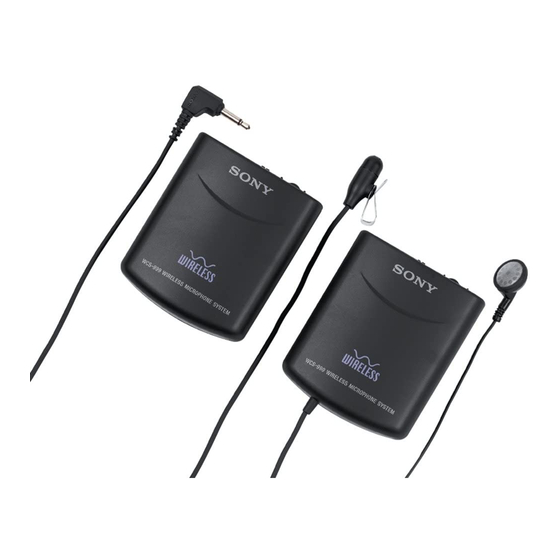
Sony WCS-999 Service Manual
Hide thumbs
Also See for WCS-999:
- Operating instructions manual (8 pages) ,
- Operating instructions manual (8 pages) ,
- Operating instructions manual (8 pages)
Subscribe to Our Youtube Channel
Summary of Contents for Sony WCS-999
- Page 1 WCS-999 SERVICE MANUAL US Model Canadian Model Ver 1.0 1999. 09 Receiver Transmitter SPECIFICATIONS WIRELESS MICROPHONE SYSTEM MICROFILM...
- Page 2 TABLE OF CONTENTS Notes on chip component replacement • Never reuse a disconnected chip component. • Notice that the minus side of a tantalum capacitor may be dam- GENERAL ............aged by heat. DISASSEMBLY ............4 ELECTRICAL ADJUSTMENTS TX Section ..............6 RX Section ..............
-
Page 3: General
SECTION 1 This section is extracted from instruction manual. GENERAL – 3 –... -
Page 4: Disassembly
SECTION 2 DISASSEMBLY Note: Follow the disassembly procedure in the numerical order given. TX BOARD 1 two screws (P2 × 6) 4 TX board 3 case (upper) 3 case (lower) 2 two claws ANTENNA SETTING TX board case (upper) cushion (lower), switch antenna case (upper) rear view –... - Page 5 RX BOARD 1 two screws (P2 × 6) 4 RX board 3 case (upper) 3 case (lower) 2 two claws ANTENNA SETTING RX board antenna case (upper) cushion (lower), switch case (upper) rear view – 5 –...
-
Page 6: Tx Section
Specified value: 70 mA to 80 mA 2. TX Frequency Confirmation Setting: The WCS-999 is a wireless microphone system operating in the 900 frequency counter TX BASE MHz. This system comprises the transmitter unit and the receiver unit. -
Page 7: Rx Section
3. TX Output Level Confirmation 5. TX Modulation Sensitivity Adjustment 3. RX Output Level Adjustment RX SECTION Setting: Setting: Setting: 1. Consumption Current Check AF OSC lead wire Setting: Frequency: 1 kHz antenna (ANT1) spectrum analyzer Output level: –50 dBV regulated dc FM RF SSG RX BASE... -
Page 8: Block Diagram – Tx Section
WCS-999 SECTION 4 DIAGRAMS 4-1. BLOCK DIAGRAM – TX Section – RV1 – 3 TX MODULATION SENSITIVITY SW51 CH-3 CH-2 CH-1 CHANNEL MIC AMP BUFFER VCO BLOCK IC1 (1/2) IC1 (2/2) ANT1 LEAD SW51-1 XTALE ANTENNA FREQUENCY BUFFER CRYSTAL PHASE... -
Page 9: Block Diagram – Rx Section
WCS-999 4-2. BLOCK DIAGRAM – RX Section – FILTER (REC OUT) LF51 10.7MHz POWER AMP IC1 (2/2) VREF FM DISCRI ANT2 LEAD FM FRONT-END, IF AMP, DET ANTENNA FRONT-END BLOCK DISCRIMI- IC1 (1/2) EXPANDER NATOR FM RF FM/AM FM IF... -
Page 11: Schematic Diagram – Tx Section
WCS-999 4-4. SCHEMATIC DIAGRAM – TX Section – • • See page 21 for Waveforms. See page 22 for IC Block Diagrams. Note on Schematic Diagram: • All capacitors are in µF unless otherwise noted. pF: µµF 50 WV or less are not indicated except for electrolytics and tantalums. -
Page 13: Schematic Diagram – Rx Section
WCS-999 4-6. SCHEMATIC DIAGRAM – RX Section – • See page 22 for IC Block Diagrams. • Waveforms – TX BASE Board – – RX BASE Board – 1 IC51 8 (XTALE) 1 IC101 2 (OUT) 200 mV/DIV, 20 ns/DIV 2 V/DIV, 5 µs/DIV... -
Page 14: Exploded Views
SECTION 5 EXPLODED VIEWS (2) RX SECTION • IC Block Diagrams NOTE: – TX BASE Board – • -XX and -X mean standardized parts, so they • Items marked “*” are not stocked since they – RX BASE Board – may have some difference from the original are seldom required for routine service. -
Page 15: Electrical Parts List
SECTION 6 RX BASE ELECTRICAL PARTS LIST NOTE: • Due to standardization, replacements in the • Items marked “*” are not stocked since they When indicating parts by reference are seldom required for routine service. parts list may be different from the parts speci- number, please include the board. - Page 16 RX BASE Ref. No. Part No. Description Remark Ref. No. Part No. Description Remark <TRIMMER> 1-162-924-11 CERAMIC CHIP 56PF 1-162-996-11 CERAMIC CHIP 0.5PF 1-141-327-11 CAP, CHIP TYPE TRIMMER 10PF 1-107-686-11 TANTALUM CHIP 4.7uF 1-141-327-11 CAP, CHIP TYPE TRIMMER 10PF 1-162-910-11 CERAMIC CHIP 0.25PF 50V 1-141-327-11 CAP, CHIP TYPE TRIMMER 10PF 1-162-910-11 CERAMIC CHIP...
- Page 17 RX BASE TX BASE Ref. No. Part No. Description Remark Ref. No. Part No. Description Remark 1-216-812-11 METAL CHIP 1/16W 1-164-346-11 CERAMIC CHIP 1-216-821-11 METAL CHIP 1/16W 1-162-970-11 CERAMIC CHIP 0.01uF 1-216-835-11 METAL CHIP 1/16W 1-216-837-11 METAL CHIP 1/16W 1-107-520-11 TANTALUM CHIP 33uF 2.5V 1-162-970-11 CERAMIC CHIP 0.01uF...
- Page 18 TX BASE Ref. No. Part No. Description Remark Ref. No. Part No. Description Remark < JACK > R103 1-216-839-11 METAL CHIP 1/16W 1-764-624-11 JACK (MIC) R104 1-216-825-11 METAL CHIP 2.2K 1/16W R105 1-218-285-11 RES, CHIP 1/16W < RESISTOR > R106 1-216-849-11 METAL CHIP 220K 1/16W...
- Page 19 Ref. No. Part No. Description Remark Ref. No. Part No. Description Remark 1-162-927-11 CERAMIC CHIP 100PF 8-952-251-90 HEADPHONE MDR-E122 SET 1-162-970-11 CERAMIC CHIP 0.01uF 1-162-970-11 CERAMIC CHIP 0.01uF 1-162-927-11 CERAMIC CHIP 100PF 1-135-180-21 TANTALUM CHIP 3.3uF 1-162-970-11 CERAMIC CHIP 0.01uF 1-162-927-11 CERAMIC CHIP 100PF 1-162-907-11 CERAMIC CHIP...
- Page 20 WCS-999 Sony Corporation 99I0519-1 9-927-161-11 Personal Audio Company Printed in Japan C 1999. 9 – 30 – Published by General Engineering Dept.


Need help?
Do you have a question about the WCS-999 and is the answer not in the manual?
Questions and answers