
Summary of Contents for Fantic Motor INTEGRA 140 TRAIL
- Page 1 INTEGRA ELECTRIC BICYCLE WITH SERVO-ASSISTED PEDALLING INTEGRA 140 TRAIL INTEGRA 160 ENDURO INTEGRA 180 ENDURO R User and maintenance handbook (translated from original language) Made in Italy...
- Page 3 Index GENERAL INDEX Section 00 - Introduction 1. INTRODUCTION............0-1 7. DESCRIPTION OF THE BICYCLE ....2-7 7.a - Brakes ..............2-7 2. MEANING OF “EPAC” - 7.b - Gear change unit ..........2-8 Electrical Power Assisted Cycle .......0-1 7.c - Frame and forks ..........2-9 3.
- Page 4 Index Section 05 - Using your bicycle Section 07 - Cleaning and Maintenance 1. GENERAL SUGGESTIONS ......5-1 1. CLEANING AND CARE ........7-1 2. USING THE GEAR CHANGE UNIT ....5-3 2. PERIODIC MAINTENANCE PROGRAM ..7-1 3. USING THE BRAKES ........5-4 3. CLEANING YOUR BICYCLE ......7-3 4.
-
Page 5: Introduction
Introduction 1. INTRODUCTION Dear Customer, This bicycle has been manufactured using the thank you for purchasing our product. highest quality materials in conformity with all Our electric bicycle is a combination of inno- the applicable standards and regulations. vation, design and comfort and has been de- signed and manufactured exclusively in Italy. -
Page 6: Description Of Symbols
Introduction 3. DESCRIPTION OF SYMBOLS This manual contains a series of symbols that N.B.: are intended to draw your attention to particu- This symbol indicates important informa- larly important information and instructions. tion designed to help you get the best out of The meaning of these symbols is explained below: your bicycle Hazard... -
Page 7: Safety Information
- Preserve this manual carefully so that - Fantic Motor reserves the right to mod- you can consult it at a later date if nec- ify this documentation in any way it essary; if ownership of the EPAC bicycle... -
Page 8: A - Correct Use
Warnings and Safety Devices 1.a - Correct use - ALWAYS use the bicycle as described in this manual and any additional - The bicycle described in this manual documentation. has been designed to be used in off- road conditions. - Using the bicycle for any other purpose than that it has been de- signed for may result in hazardous riding conditions, falls and acci-... -
Page 9: B - Improper Use
Warnings and Safety Devices 1.b - Improper use We strongly recommend that you DO NOT use bicycle racks as this - As has already been described, you may damage the bicycle safe- must ensure your bicycle has been fit- ty components. Failure of such ted with all the accessories required by components may result in haz- the locally applicable regulations be-... -
Page 10: D - Residual Hazards
Warnings and Safety Devices - The bicycle can be used to reach high been fitted with the additional equip- speeds for prolonged periods. The ment required by the locally applicable user must make sure that he/she has legal regulations. In Italy and Germany, enough stamina to control the bike these requirements are covered by the safely for a period of almost two hours. - Page 11 Warnings and Safety Devices Also, it is extremely important • Keep the bicycle and battery charger to deflate the bicycle tyres when out of the reach of children and ani- transporting it inside a motor ve- mals. hicle. • Ensure that the battery charger does Ensure you park in a shaded area not come into contact with water or and that the ambient tempera-...
-
Page 12: E - First Use
Warnings and Safety Devices • Do not leave your bicycle inside motor ve- hicles that are exposed to direct sunlight. The brake disks may reach very high temperatures following a long descent. · Do not touch the brake disks immediately fol- front lowing a descent. -
Page 13: Taking Care Of The Battery Pack
Warnings and Safety Devices 2. TAKING CARE OF THE BATTERY PACK Do not attempt to carry out any op- erations other than those described Improper use of lithium bat- in this manual on your own. For any teries may result in fires, ex- operations not described in this doc- plosions or chemical hazards. -
Page 14: Modifications
Warnings and Safety Devices 4. PRECAUTIONS FOR MOUNTING ACCESSORIES OR COMPONENTS FOR MODIFICATIONS The use of non-standard ac- - Do not attempt to install accessories or cessories and/or components equipment on the bicycle or modify it on your bicycle may damage it and any way on your own initiative. -
Page 15: Warranty Conditions
Fantic Motor. mally excluded from the terms of the warranty. The warranty and conditions may be trans- - Fantic Motor reserves the right to supply ferred to the new owner in the event that and/or install components that may differ... -
Page 16: Identification Plate
Warnings and Safety Devices 7. IDENTIFICATION PLATE Each bicycle is equipped with an identification plate positioned in the rear part of the chassis. Please communicate the serial number indicated on the plate whenever you ask for assistance or to order spare parts. -
Page 17: External Dimensions
Description and Technical Data 1. EXTERNAL DIMENSIONS (M size) min ˜ 590mm MAX ˜ 770mm ˜ 280 mm ˜ 1260 mm ˜ 1970 mm ˜ 740 mm ˜ 780 mm ˜ 800 mm INTEGRA 140 INTEGRA 160 INTEGRA 180 2. STANDARD EQUIPMENT Once you have removed your bicycle from its pos. -
Page 18: Identifying The Bicycle Components
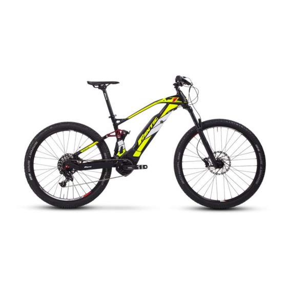
Description and Technical Data 3. IDENTIFYING THE BICYCLE COMPONENTS Front tyre 20 Handlebar tube 1a Tyre valve 21 Rear tyre Front brake lever 22 Wheel cover strip Rear brake lever 23 Gear change unit Left hand grip 24 Chain Function selector buttons 25 Handlebar joint Handlebars 26 Crown guard (optional - not shown) - Page 19 Description and Technical Data 140 TRAIL 160 ENDURO 180 ENDURO R Ed. 1 - 11/2017...
-
Page 20: Technical Data
Description and Technical Data 4. TECHNICAL DATA 140 TRAIL MODEL Motor 36 Volt Brose central motor, Max power: 250 Watt, Torque: 90 Nm Battery Lithium-ion battery, 36 Volt, 630 Wh Display Multifunctional display, with integrated power management unit Chassis Aluminium chassis, CNC particulars. Sizes S - M - L Suspension fork Rock Shox Recon Silver 140 Shock absorber... - Page 21 Description and Technical Data 160 ENDURO MODEL Motor 36 Volt Brose central motor, Max power: 250 Watt, Torque: 90 Nm Battery Lithium-ion battery, 36 Volt, 630 Wh Display Multifunctional display, with integrated power management unit Chassis Aluminium chassis, CNC particulars. Sizes S - M - L Suspension fork Rock Shox Yari RC 160 Boost Shock absorber...
- Page 22 Description and Technical Data 180 ENDURO R MODEL Motor 36 Volt Brose S central motor, Max power: 250 Watt, Torque: 90 Nm Battery Lithium-ion battery, 36 Volt, 630Wh Display Multifunctional display, with integrated power management unit Chassis Aluminium chassis, CNC particulars. Sizes S - M - L Suspension fork Rock Shox Lyrik RC 180 Boost Shock absorber...
-
Page 23: Removing The Packaging
Description and Technical Data 5. REMOVING THE PACKAGING 6. OPTIONAL ACCESSORIES Before shipping, the bicycle is protected with Optional accessories are available from your bubble wrapping and packaged in order to vendor, in particular, the components neces- ensure that if reaches you in perfect condition. sary to adapt your bicycle for use on public Remove the packaging carefully and dispose roads. -
Page 24: B - Gear Change Unit
Description and Technical Data Operating the brake levers too sharply may cause the wheels to lock and ex- pose the rider to the rider of falling. 7.b - Gear change unit The bicycle is fitted with a derailleur gear change system, consisting of a crank-set with a front chain-ring and a cog-set with 11 individual sprockets. -
Page 25: C - Frame And Forks
Description and Technical Data 7.c - Frame and forks The bike is equipped with a frame complete of a rear shock absorber and an incorporated amortised fork. Both the rear shock absorber and the front fork are equipped with an adjustment system, a blocking one and an air valve to adjust them depending on the user’s weight. -
Page 26: D -Wheel Units
Description and Technical Data 7.d - Wheel units The wheel units are defined as follows “front wheel” “rear wheel”. The units consist of: - hub; - sprocket set (or cog-set) (rear hub only); - brake disk; - spokes; - wheel rim; - wheel rim cover strip;... -
Page 27: E - Electrical Devices
Description and Technical Data 7.e - Electrical devices For information about the components of the electrical power-assisted pedalling system and how to use them, see Section “06”. 7.f - Battery pack The battery pack must be installed in the ded- icated supported mounted on the frame. - Page 28 Description and Technical Data 2-12 Ed. 1 - 11/2017...
-
Page 29: First Time
Checks and inspections 1. USING YOUR BICYCLE FOR THE FIRST TIME Risk of heavy falls and serious ac- Make sure that the vendor has compiled all the sections of the test and inspection report be- cidents. The bicycle is supplied to fore taking delivery of your bicycle. -
Page 30: Checking Wheels And Tyres
Checks and inspections Visually inspect all the bicycle If you find any defects, contact components for incisions, break- your vendor. ages, deep cracks and any other mechanical damage. 3. CHECKING WHEELS AND TYRES 3.a - Checking wheel fastenings Check the wheels one at a time by attempting to rock them from side to side while respecting the direction of travel;... -
Page 31: C - Checking The Tyre Valves
Checks and inspections 3.c - Checking the tyre valves OK ! If the bicycle is ridden when the tyre pressure is too low, it may displace the position of the tyre and inner tube on the wheel rim, so that the valve assumes an oblique position. -
Page 32: E - Checking The Wheels
Checks and inspections Unscrew the safety cap (2). Check the pressure using a pressure gauge, or a pump with a built-in pressure gauge. If necessary, inflate or deflate the tyre (pressing against the internal valve “3”). Replace the safety cap (2). 3.e - Checking the wheels Raise the front wheel and rotate it manually. -
Page 33: G - Checking The Handlebars
Checks and inspections 3.g - Checking the handlebars If the handlebars and the han- dlebar joint are damaged or have not been installed correctly it may result in hazardous riding conditions, falls and accidents. If you observe any defects on these parts, or in case of doubt, do not use your bicycle and contact the vendor or a quali-... -
Page 34: H - Checking The Brakes
Checks and inspections 3.h - Checking the brakes Heavy fall hazard Faulty brakes can always result in hazardous riding conditions, falls and acci- dents. A brake malfunction may MIN 10 mm endanger the life of the rider. Take great care when checking you braking system. -
Page 35: Mountings
Checks and inspections 3.i - Checking the chain and the crank mountings This check must be carried out by two people: the first raises the rear wheel so that it is not in contact with the ground, while the second rotates the right hand pedal crank clockwise. -
Page 36: M -Checking The Lights (If Fitted)
Checks and inspections 3.m - Checking the lights (if fitted) This paragraph applies only if the bicycle was equipped for use on public roads when it was purchased, or if the accessories have been fit- Switch the lights on and secure that both the ted at a later date (see Section “01”). -
Page 37: Tightening Torque
Checks and inspections 4. TIGHTENING TORQUE If no specific information has been provided by The corresponding tightening torque (in Nm) is the manufacturer, refer to the following tightening stamped into the heads of the bolts and screws. torque values. Threaded joint Thread Tightening torque (Nm) Pedals... - Page 38 Checks and inspections 3-10 Ed. 1 - 11/2017...
-
Page 39: Mounting The Pedals
Assembly and Adjustments Some of the operations described in the section may be carried out by the user without outside assistance. Only attempt to carry out these procedure if you have the correct tools. 1. MOUNTING THE PEDALS For reasons of space, the bicycle is shipped without the pedals mounted. -
Page 40: Adjusting The Handlebars
Assembly and Adjustments 2. ADJUSTING THE HANDLEBARS For reasons of space, the bicycle is also shipped with the handlebars rotated so that they are aligned with the frame. · Using a 6 mm Allen key, loosen the screws (1). · Rotate the handlebars so that they are perpendicular to the frame. -
Page 41: Adjusting The Saddle
Assembly and Adjustments 3. ADJUSTING THE SADDLE 3.a - For “140” version • Regulating the height Loosen the saddle support tube locking collar (using a 6 mm Allen key). Regulate the height of the saddle by moving the support tube in the desired direction. Min 10cm Do not extract the saddle sup- port tube past the indicator mark... -
Page 42: B - For "160" And "180" Versions
Assembly and Adjustments 3.b - For “160” and “180” versions • Seat tube adjustment Loosen the saddle locking screws (using a 6 mm Allen key). Adjust the angle of the saddle as desired. Do not raise the seat tube above the “0”... -
Page 43: Assembly And Adjustments
Assembly and Adjustments • Regulating height The seat height adjustment can be performed while being seated on the seat itself. To adjust the seat height press the lever (1), then push the seat downwards or reduce pres- sure to make it raise. Once you’ve reached the desired height, re- lease the lever (1). -
Page 44: And Angle
Assembly and Adjustments 3.c - Regulating the saddle position and angle Loosen the saddle locking screws (using a 6 mm Allen key). Adjust the angle of the saddle as desired. Tighten the screws respecting the correct torque values (see paragraph “4” - Section “03”). 4. -
Page 45: Adjusting The Gear Change Lever
Assembly and Adjustments · Tighten the screws respecting the correct torque values (see paragraph “4” - Section “03”). 5. ADJUSTING THE GEAR CHANGE LEVER If you wish to adjust the position of the gear change lever: · loosen the lever locking screw (using a 5 mm Allen key). - Page 46 Assembly and Adjustments Ed. 1 - 11/2017...
-
Page 47: General Suggestions
Using your bicycle 1. GENERAL SUGGESTIONS Your bicycle is designed to be used either in the To select the riding mode, see paragraph “9” - traditional way, or with power-assisted pedalling. Section “06”. We recommend that you familiarize yourself with your bicycle before using power-assisted pedalling. - Page 48 Using your bicycle Falling hazard and risk of acci- After riding your bicycle, allow the dents caused by an unexpected brake disks to cool down for 5 min- movement. utes before touching them. · Cycle with care, always respect the Do not attempt to cool them down recommended maintenance inter- using water or other liquids, as this...
-
Page 49: Using The Gear Change Unit
Using your bicycle 2. USING THE GEAR CHANGE UNIT In order to prevent the motor traction from damaging the chain as it transfers from one sprocket to another, reduce the pressure exerted on the pedals when changing gears. The bicycle is fitted with derailleur gears. Each time the rider changes gears the chain is transferred to a different sprocket. -
Page 50: Using The Brakes
Using your bicycle 3. USING THE BRAKES To operate one of the brakes, pull the corre- sponding lever towards the handlebars. Risk of falls and accidents. Braking too sharply may cause the wheels to lock causing the bicycle to skid or tip over. ·... -
Page 51: Using Your Bicycle
Using your bicycle 4. USING YOUR BICYCLE Grasp the left hand grip firmly with your left hand, and right hand grip firmly with your right hand. Operate both the brake levers. To move forward, place your left foot on the left hand pedal and your right foot on the right hand pedal. - Page 52 Using your bicycle Falls may result in short circuits If you notice flames or smoke in the battery pack, causing it to coming from the battery pack, catch fire. stop the bicycle immediately. · Following a fall or an accident, leave Put the fire out using an extinguish- the bicycle outdoors for an hour, er, if possible.
-
Page 53: How To Transport Your Bicycle
Using your bicycle 6. HOW TO TRANSPORT YOUR BICYCLE In order to transport your bicycle (for example, by car), it may be necessary remove the front and/or rear wheel. Refer to following illustrates below and in Sec- tion “01” for an explanation of how to perform these operations. -
Page 54: Suspension Fork
Using your bicycle 7. LOCKING/RELEASING THE FRONT SUSPENSION FORK Under certain riding conditions it is possible to block the front fork by turning the ring “1” as shown in the picture. Each mark corresponds to a different locking. To unlock the fork turn the ring “1” in the oppo- site direction. - Page 55 Using your bicycle PUMP • If the fork lowers less, deflate air by pressing the pump button. • Adjust the fork return speed by operating on the ring under the stem. Adjustment screw type “A” Adjustment screw type “B” Ed. 1 - 11/2017...
-
Page 56: Locking/Releasing The Rear Shock Absorber
Using your bicycle 9. LOCKING/RELEASING THE REAR SHOCK ABSORBER For particular use needs it is possible to block the rear shock absorber by turning the ring “1” on “ ” as shown in the picture. Each mark corresponds to a different locking. To unlock the shock absorber turn the ring “1”... - Page 57 Using your bicycle • If the shock absorber lowers more, it is necessary to remove the cap “2” and, using an appropriate not supplied pump, blow air inside the shock ab- sorber (max 325 psi). 325 MAX psi 140 TRIAL 160 ENDURO PUMP •...
-
Page 58: Advised Sag
Using your bicycle For “180” version • Compression damping controls the shock ab- sorber compression speed in slow compression travel, such as the pilot weight transfer, small im- pacts and turns, thing which improves control and performance. • An excessive compression damping makes sus- pension too rigid for impacts. -
Page 59: Notes On Battery Duration
Using your bicycle 12. NOTES ON BATTERY DURATION Battery duration may vary significantly (from 20 to 150 km) depending on the type of use and the age of the batteries (on average, battery duration is reduced by approx. 40 % after 3 or 4 years). The main factors that affect battery duration are: Factor Relevance... - Page 60 Using your bicycle 5-14 Ed. 1 - 11/2017...
-
Page 61: Getting Started
Using power assisted pedalling 1. GETTING STARTED This paragraph summarizes the most important information necessary for a correct use of the pow- er-assisted pedalling system. Make sure that the battery pack is fully charged (see paragraph “4” of this section). When charging the battery, it may be re- moved or left in its housing on the bicycle. -
Page 62: From Its Support
Using power assisted pedalling 2. REMOVING THE BATTERY PACK FROM ITS SUPPORT Disconnect the connector from the battery pack. Completely unscrew the battery fixing screw until you remove it. Raise the battery pack until you release it from its support and remove it. Place the battery pack on a flat and dry surface. -
Page 63: Charge The Battery Pack
Using power assisted pedalling 3. CHARGE THE BATTERY PACK 3.a - Activating the battery pack before use The battery pack is supplied partially charged. For this reason, it should be tested before recharg- ing it. Press the button (1) to activate the battery. ·... -
Page 64: On Its Support
Using power assisted pedalling Connect the power cable to the electrical mains socket. Make sure that the electrical mains supply voltage corresponds to the value indicated on the battery charger data plate. Connect the small plug on the power cable to the socket on the battery charger. - Page 65 Using power assisted pedalling Delicately push the battery pack downwards to lay it in its specific support. Connect the connector to the battery pack. Completely screw the fixing screw to lock the battery. Ed. 1 - 11/2017...
-
Page 66: Display
Using power assisted pedalling 5. DISPLAY 5.1 - Function buttons T1. Display switching on/off (assisted pedalling system ON/OFF) T2. Lights switching on/off(if present and connected) - Short pressing: the light turns on. - Longer pressing (more than 2 seconds): the light turns off. - In automatic mode: the light turns on and off depending on the surrounding level of light. - Page 67 Using power assisted pedalling The other pages show the following informa- tion: 1- Page icon. 2- Horizontal browsing position. 3- Page content. 4- Vertical browsing position (it refers to oth- er pages and shows the current position) . Push power Shows the power (in watts) generated by the cyclist for the assisted pedalling activation.
- Page 68 Using power assisted pedalling Travelled distance -> Maximum speed Shows the maximum reached speed referred to the travelled distance. Travelled distance -> Reset Press the joystick “T3”, the writing “RESET” is shown. Press the joystick “T3” again to reset all the val- ues (distance, average and maximum speed) to “0”.
-
Page 69: Pedalling Assistance Activation And Level
Using power assisted pedalling Automatic light (Only usable if the headlights are present and connected) Use this page to activate the light turning on/ off automatic mode (the light turns on and off depending on the surrounding light level). If the automatic mode is active, the “light” sym- bol on the main page is shown with an “A”... - Page 70 Using power assisted pedalling “minimum” pedalling assistance level > > > “medium” pedalling assistance level > > > “maximum” pedalling assistance level > > > 6-10 Ed. 1 - 11/2017...
-
Page 71: Push Help" Function
Using power assisted pedalling - To shut off the pedalling assistance function it is enough to press the button “T4” once or more times until all the marks on the display are turned off; the function immediately de- activates. pedalling assistance “deactivated” > > > Setting Assistance % In the event of a prolonged use in severe con-... -
Page 72: Usb Connection
It is possible to connect an external device (mobile, smartphone, mp3 player etc.) to the Usb port. Once the link has been performed, the new connection is shown on the device. Fantic Motor takes no responsibility for eventual damages caused to the external device connected to the Usb port. -
Page 73: Cleaning And Care
Cleaning and Maintenance The operations described in this section may be carried out by the user. All other operations MUST be carried out by the vendor or qualified personnel. 1. CLEANING AND CARE Always disconnect the battery pack before carrying out main- tenance and/or cleaning opera- tions. - Page 74 Cleaning and Maintenance • After completing 300 to 500 Km Check the following parts for signs of wear and It is important to bear in mind that some tear (contact your vendor in order to replace lubricants and maintenance products them if necessary): may not be suitable for use on your bi- Chain.
-
Page 75: Cleaning Your Bicycle
Cleaning and Maintenance 3. CLEANING YOUR BICYCLE Proceed as follows: Clean the wheel rims and brake disks using a suit- Disconnect the battery pack and remove it; able degreasing product (consult your vendor). remove the display (see paragraph “7.a” - Section “06”). -
Page 76: Parking Your Bicycle
Cleaning and Maintenance 4. PARKING YOUR BICYCLE When the bicycle is resting on its stand or against a wall, fence or When the bicycle is stationary, lower the stand railings, even the slightest con- using your right foot until it clicks into place. Rotate the handlebars so that they are facing tact may cause it to tip over. -
Page 77: B - Removing The Front Wheel
Cleaning and Maintenance 5.b - Removing the front wheel Pull the eccentric lever so that it moves away from the wheel hub. The lever can be rotated by approx. 180° around its axis. Push the lever towards the hub to “hook it” to the ring groove. -
Page 78: C - Mounting The Front Wheel
Cleaning and Maintenance Insert the transport block (f - supplied) be- tween the brake pistons. Never operate the hydraulic brakes when the wheel unit has been removed. Use the trans- port blocks (f - supplied) and remember to re- move them before replacing the front wheel. Take care no to lose the two spacers (d). -
Page 79: D -Removing The Rear Wheel
Cleaning and Maintenance Push the lever towards the hub to “hook it” to the ring groove. Turn the eccentric lever until hooking the pin (by hand). Raise the lever and push it until comes to rest against the fork. Check that the wheel has been mounted se- curely and correctly. - Page 80 Cleaning and Maintenance Push the gear change unit forward and press the button (t) to lock it in place. The tension on the chain is released. Using a 6 mm wrench, unscrew the axle pin from the brake side. Slide the axle pin out of the frame. Disengage the chain from the sprocket and re- move the wheel.
-
Page 81: E - Mounting The Rear Wheel
Cleaning and Maintenance 5.e - Mounting the rear wheel Remove the transport block (f) from the brake pistons. Do not operate the rear brake lever. Insert the wheel between the frame forks, posi- tioning the chain on the smallest sprocket and making sure that the brake disk is positioned between the brake pistons. -
Page 82: Flat Tyre
Cleaning and Maintenance Push the gear change unit forward to release it. Make sure that the wheel turns freely. 6. FLAT TYRE In the event of a flat tyre, first of all, attempt to re-inflate it, if the tyre deflates again it may be punctured or damaged. - Page 83 Cleaning and Maintenance Identify the cause of the puncture: · Inflate the defective inner tube using the bi- cycle pump. · Attempt to find the point where the air es- capes. · If it is possible to identify the air leak, twist the inner tube around so that the valve is pointing inwards.
-
Page 84: Other Operations
Cleaning and Maintenance Avoid touching the inner surface Make sure that the tyre is positioned centrally of the tyre with your fingers since on the wheel rim and that the inner tube does there may still be sharp objects not protrude at any point. lodged in the tyre that could Inflate the inner tube to the recommended cause cuts or lacerations. -
Page 85: Troubleshooting
Troubleshooting 1. TROUBLESHOOTING If you encounter problems while riding your bicycle, first check whether the fault is described in the following tables. This table is designed to help you identify the correct solution without taking your bicycle to the authorized vendor. -
Page 86: Error Codes
Troubleshooting Problem Possible cause Possible solution The display indicates an error A system error is present. Consult the following table. code. 2. ERROR CODES Check whether the error code that appears on the display is included in the table and, if so, proceed as indi- cated. - Page 87 Troubleshooting Problem Possible cause Possible solution Motor current measurement error. Turn the system off completely and turn it back on using the button T4 on the Control Panel. If the problem persists, please contact the dealer or the retailer. The software has been reset. Turn the system off completely and turn it back on using the button T4 on the Control Panel.
- Page 88 Troubleshooting Problem Possible cause Possible solution Pedal rotation not detected. Turn the system off completely and turn it back on using the button T4 on the Control Panel. If the problem persists, please contact the dealer or the retailer. Force applied to pedals not detected. Turn the system off completely and turn it back on using the button T4 on the Control Panel.
-
Page 89: Periodic Inspection Forms
Periodic inspections 1. PERIODIC INSPECTION FORMS Ed. 1 - 11/2017... - Page 90 Periodic inspections Ed. 1 - 11/2017...
-
Page 91: Delivery Documents
Delivery documents 1. DELIVERY DOCUMENTS This bicycle was delivered to the customer (after final assembly and adjustments), NOT ready for use. In particular, before the delivery, the following points needs to be checked: Lights (if fitted). Front and rear brakes. Front suspension fork (if fitted) (regulated according to the physical characteristics of the customer). - Page 92 Delivery documents VENDOR’S DETAILS Name, Surname: ___________________________________________________________________________ Address: _________________________________________________________________________________ Postcode, Town/City, Province/State/County: ____________________________________________________ Telephone/Mobile: __________________________ Fax: ______________________________________ Email: ____________________________________________________________________________________ __________________________________________ ________________________________________ Place, date Signature Vendor’s stamp By signing this document the customer declares that he/she has received the bicycle and the associated documentation in perfect condition, and that the vendor has provided him/ her with all the necessary information and explanations regarding the correct use of the bicycle and the accessories installed on it.
- Page 94 Fantic Motor s.r.l. Via Enzo Tarantelli, 7 31030 Dosson di Casier (TV) - Italy Tel. +39 0422 634192 Fax. +39 0422 630491 info@fanticmotor.it commerciale-bike@fanticmotor.it Code: B+FEN97-MB09000335 Ed. 1 - 11/2017...
Need help?
Do you have a question about the INTEGRA 140 TRAIL and is the answer not in the manual?
Questions and answers