Table of Contents
Advertisement
Quick Links
INSTALLATION AND OWNER'S MANUAL
Serial #:
Date Installed:
Your Dealer:
MODEL T
Trolley Door Operator
UL 325 and UL 991 Listed
READ THIS MANUAL CAREFULLY
BEFORE INSTALLATION OR USE.
SAVE THESE INSTRUCTIONS.
As of date of manufacture,
meets all ANSI/UL 325
Safety Requirements for
Vehicular door operators.
Advertisement
Table of Contents

Related Manuals for PowerMaster T

Summary of Contents for PowerMaster T
- Page 1 INSTALLATION AND OWNER’S MANUAL MODEL T Trolley Door Operator UL 325 and UL 991 Listed Serial #: Date Installed: READ THIS MANUAL CAREFULLY As of date of manufacture, Your Dealer: meets all ANSI/UL 325 BEFORE INSTALLATION OR USE. Safety Requirements for SAVE THESE INSTRUCTIONS.
- Page 2 Table of Contents Model T Drawbar Operator Product Features ....................3 Preparation ......................4 Component Identification ..................5 Important Installation Notes (Things to do Before & During Installation) ....6 Installation Instructions ................. 7-14 Rail/Track Assembly ..................7 Operator Assembly ..................8-9 Mounting the Operator ................10-13 Setting the Limit Switches ................14...
-
Page 3: Product Features
Manual Release: Permits manual operation of the door in the event of a power failure. The Model T operator is equipped with a door arm disconnect to aid in manual operation. Use of this feature will not affect the limit switch adjustment. -
Page 4: Preparation
Model T Drawbar operators are used in the following applications: • Continuous Duty, Indoor Commercial installations only • Up to 22 foot high doors with a maximum area of 480 square feet for 3/4HP, 360 square feet for 1/2HP, and 270 square feet for 1/3HP. Maximum area slightly higher for lighter doors - consult factory. -
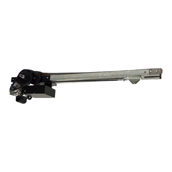
Page 5: Component Identification
COMPONENT IDENTIFICATION UPPER HALF TROLLEY ASSEMBLY CHAIN CONNECTING FRONT TRACK LINK CHAIN BRACKET THREE BUTTON LOWER HALF STATION TROLLEY ASSEMBLY SPREADER CHAIN BARS TAKE-UP BOLT IDLER ROLLER ASSEMBLY HARDWARE PACKAGE TRACK RAILS DOOR STRAIGHT CONNECTING ARM WITH ARMS DISCONNECT OPERATOR DOOR POWER HEAD BRACKET... - Page 6 Check the door manufacturer’s instruction manual for a bracing procedure or the availability of a Reinforcement Kit. • PowerMaster Model T Drawbar operators are Commercial Vehicular Door Operators, and as such, are NOT recommended for pedestrian traffic. In installations where it is known that the pedestrians will be nearby, ensure a pedestrian door is available for entrance and exit to the building.
-
Page 7: Installation Instructions
INSTALLATION INSTRUCTIONS SPRINGS, PULLEYS, CABLES AND MOUNTING HARDWARE USED TO BALANCE YOUR GARAGE DOOR ARE UNDER EXTREME TENSION AT ALL TIMES AND CAN CAUSE SEVERE INJURY OR WARNING DEATH IF DISTURBED. DO NOT ATTEMPT ADJUSTMENT. TRACK ASSEMBLY Before starting assembly of the operator track, check for proper length. The tracks supplied may be longer than required for the door height. -
Page 8: Operator Assembly
OPERATOR ASSEMBLY 1. Install Trolley Slide Assembly on Track Assembly with Chain Take-up Bolt [#7] pointing towards end of track where Power Head [#8] will be mounted as shown in Figure 4. 2. Mount Power Head to Track Assembly using four 3/8 x 3/4 Long Hex Head Bolts, four 3/8 Lock Washers and four 3/8 Hex Nuts, as shown in Figure 4. - Page 9 FIGURE 4 (4) 3/8 X 3/4” LG. TROLLY SLIDE HEX HEAD BOLTS ASSEMBLY TRACK ASSEMBLY (4) 3/8” LOCK WASHERS (4) 3/8” POWER HEAD HEX NUTS FIGURE 5 CHAIN CONNECTING LINK LOCK NUT CHAIN ADJUSTING TROLLEY ASSEMBLY DRIVE TAB CHAIN CONNECTING LINK LOCK WASHER DRIVE CHAIN Unit is shown in the inverted position to facilitate assembly of trolley track and...
-
Page 10: Mounting The Operator
TO AVOID DAMAGE TO THE DOOR AND OPERATOR, ENSURE WARNING ALL LOCKS ARE DISABLED. USE AN INTERLOCK SWITCH IF A LOCK IS REQUIRED TO RETAIN FUNCTIONALITY. MOUNTING THE OPERATOR 1. Locate the center of the door and mark a line on the wall directly above the door. Extend this line approximately 20”... -
Page 11: Mounting The Operator
WARNING BEFORE PROCEEDING, RE-CHECK ALL BOLTS, THE FRONT MOUNTING SURFACE MUST NUTS AND LAG BE SOUND AND SECURE. IF NECESSARY, SCREWS AND ENSURE PROVIDE REINFORCEMENT IN THIS AREA THEY ARE TIGHT! BEFORE MOUNTING THE OPERATOR RAIL FRONT MOUNTING BRACKET. 4. Raise operator and Track Assembly into mounting position, as shown in Figure 10. - Page 12 CENTER LINE 3/8” HEX HEAD BOLTS CENTER OF DOOR (BY OTHERS) LINE OF 3/8” LAG BOLTS DOOR (BY OTHERS) ANGLE IRON MOUNTING PAD WOOD BLOCK MOUNTING PAD OVERALL LENGTH = DOOR HEIGHT PLUS 4’9” LEVEL 3-1/2” MIN. ANGLE IRON SUPPORTS (BY OTHERS) SIDE BRACE (2) PIECES.
- Page 13 FIGURE 11 3/8” X 1-1/4” LG. HEX HEAD BOLTS 3/8” LOCKWASHERS AND NUTS DOOR CENTER LINE DOOR ARM ASSY. 3/8” NUTS 3/8” X 1-1/4” LG. HEX HEAD BOLT (BY OTHERS) FIGURE 12...
-
Page 14: Setting The Limit Switches
TO AVOID RISK OF ENTRAPMENT AND POSSIBLE DAMAGE WARNING TO THE DOOR AND OPERATOR, THE LIMITS MUST BE ADJUSTED BEFORE APPLYING POWER TO THE OPERATOR. SETTING THE LIMIT SWITCHES 1. Remove the cover on the electrical enclosure. There are two limit nuts on the threaded limit shaft that move laterally along the shaft as the operator opens and closes the door. -
Page 15: Electrical Wiring Instructions
NOTE: All T operators are pre-wired to accept reversing edge components. To comply with UL requirements, one of these systems must be installed and wired to the operator. Refer to Figures 9 and 10 for Edge Component Wiring and Installation. -
Page 16: Accepted Safety Equipment
CPT223 with suffix T2 provided with interface module model Signature Module model SM-102. • Optical Door Edge Sensor and Photo Eye manufactured by Fraba Inc. models OPTOEDGE, OPTOEYE; Part Nos. OSE-T, OSE-R, OSE-P, OPE. SEE MANUFACTURER’S INSTRUCTIONS FOR INSTALLATION OF THIS SAFETY EQUIPMENT. - Page 17 IMPORTANT SAFETY INSTRUCTIONS FOR OWNER TO REDUCE THE RISK OF SEVERE INJURY OR DEATH: READ AND FOLLOW ALL INSTRUCTIONS! WARNING • NEVER let children operate or play with door controls. Keep remote control away from children. • ALWAYS keep a moving door in sight and keep people and objects away from the door area until the door is completely closed.
-
Page 18: Operation And Adjustment Instructions
OPERATION AND ADJUSTMENT INSTRUCTIONS CLUTCH ADJUSTMENT WARNING The clutch serves to protect the door, the RISK OF ENTRAPMENT THAT MAY electric operator and other equipment from RESULT IN SEVERE INJURY OR DEATH! undue stress or damage caused by starting DISCONNECT POWER TO THE OPERATOR forces and/or an obstruction to the door. -
Page 19: Testing
WARNING WARNING ALWAYS DISCONNECT POWER TO DO NOT STAND UNDER DOOR TO THE OPERATOR BEFORE SERVICING, TEST REVERSING EDGE. USE A CONNECTING ACCESSORY DEVICES CORRUGATED BOX OR SIMILAR OR MAKING ADJUSTMENTS. OBJECT. TESTING Following installation, the operator MUST engage when the release cord is pulled and be tested and respond correctly to all the door arm assembly releases from the controls as specified on the wiring diagram. -
Page 20: Maintenance
MAINTENANCE SUGGESTIONS WARNING Normally, very little maintenance is required. A monthly visual inspection must be made for DO NOT STAND UNDER DOOR TO TEST REVERSING EDGE. USE A CORRUGATED loose or missing hardware and for excessive BOX OR SIMILAR OBJECT. slack in the V-belt and Jackshaft Chain. -
Page 21: Trouble Shooting Chart
TROUBLE SHOOTING CHART SYMPTOM POSSIBLE CAUSE SOLUTION Door jammed or obstructed. Check manual operation of door. Motor runs but Trolley disconnected from drive Reconnect door arm to trolley traveler. door does not with door arm release. move Check clutch adjustment. Check belt for Clutch slipping/ V-Belt slipping wear and proper tension. - Page 22 Notes...
-
Page 23: Warranty
Limited 2-Year Warranty MECHANICAL PARTS: PowerMaster warrants all DOOR OPERATORS (MG, H, J, T, SL categories) to be free of defects in materials and workmanship for a period of two (2) years from date of manufacture, provided that product has been registered. A one year warranty applies if product has not been registered. - Page 24 Need Technical Support? Visit: www.vepower.net/faqs Call us toll free @ 1-800-243-4476 Email us: PMtech@VEpower.net www.facebook.com/PowerMasterOperators Scan QR Code with your Smart phone to find us on the web! MANUFACTURED BY V.E. POWER DOOR CO,INC. WWW.VEPOWER.NET REV 2017-0920...
Need help?
Do you have a question about the T and is the answer not in the manual?
Questions and answers