
Subscribe to Our Youtube Channel
Summary of Contents for Denkovi DAEnetIP3
- Page 1 DAEnetIP3 User Manual DAEnetIP3 User Manual Date: 02.11.2017 Describes DAEnetIP3 firmware version 2.0.0...
- Page 2 DAEnetIP3 User Manual Content 1. Basic features ......................6 2. DAEnetIP3 PCB ...................... 7 3. Technical parameters ....................8 4. Application examples ....................9 5. Default Settings ..................... 13 5.1. Digital outputs (Port A) ................... 13 5.2. Digital Inputs (Port B) ..................13 5.3.
- Page 3 10.3.5. Working mode ..................42 10.4. Examples ...................... 42 10.4.1. Example 1: Two DAEnetIP3 controllers connected via UTP cable ..42 10.4.2. Example 2: Two DAEnetIP3 controllers connected via WLAN ....43 10.4.3. Example 3: Two DAEnetIP3 controllers connected via LAN ....44 10.4.4.
- Page 4 18.3. DAEnetIP3 power jack and RJ-45 port ............94 18.4. DAEnetIP3 Led indicators ................95 18.5. DAEnetIP3 Wi-Fi led indicator and external antenna connector ....96 19. Appendix 2. Connecting the controller to LAN/WLAN/WAN ........ 97 19.1. UTP cable connection with PC for first time ..........97 19.2.
- Page 5 24.5. Loading default settings via DAEnetIP3 socket command ......112 25. Appendix 8. Firmware upgrade ................113 26. Appendix 9. How to create Virtual Serial Port for DAEnetIP3 ......114 27. Appendix 10. Example commands ..............117 27.1. Commands for Digital Outputs (Port A) ............117 27.2.
-
Page 6: Basic Features
DAEnetIP3 User Manual 1. Basic features DAEnetIP3 is multifunctional standalone Ethernet / Wireless device for remote management and control with Virtual Serial Port, TCP/IP socket based protocol, HTTP API, Web, Telnet and serial commands access. Many controllers can be connected over LAN/WLAN/WAN or serial network. It can work standalone (without PC). -
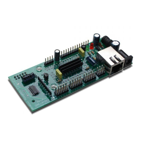
Page 7: Daenetip3 Pcb
DAEnetIP3 User Manual 2. DAEnetIP3 PCB... -
Page 8: Technical Parameters
DAEnetIP3 User Manual 3. Technical parameters Table 1. Technical parameters Parameter Value Digital outputs count Analog inputs count 8 (10bit ADC, Vref=2.048V) with 100 kOhm pull-down resistor to GND Digital inputs count Default settings jumper LED (Link, Status, Power On) -
Page 9: Application Examples
DAEnetIP3 User Manual 4. Application examples DAEnetIP3 has 16 digital outputs that are suitable for controlling electrical devices over the local network or Internet. Using its Wi-Fi 802.11 communication module it is possible to control different electrical devices wireless. Figure 1. Controlling electrical devices with DAEnetIP3 remotely DAEnetIP3 has 8 analog inputs (Vref=2.048V / 10bit resolution) and 8 digital... - Page 10 DAEnetIP3 gives possibilities to built up to 8 thermostats, using all the 8 analog inputs and 8 of the digital outputs. The flexibility of DAEnetIP3 allows to attach each analog input to each digital output. The combination of different I/O modes makes several variations for the thermostat.
- Page 11 Figure 5. Simple PLC DAEnetIP3 has UART port (RX,TX and Direction pin) allowing to create RS485 network. DAEnetIP3 acts like a bridge between the two types of networks. This is suitable in cases where single IP address must access many DAEnetIP3 controllers.
- Page 12 DAEnetIP3 this is not a problem, because each controller may send message to another one, saying “turn digital output 1 in logical one”. Each DAEnetIP3 may be controller by up to 5 another DAEnetIP3 controllers at the same time. The communication is done over the LAN/ WLAN.
-
Page 13: Default Settings
DAEnetIP3 User Manual 5. Default Settings These are the default (factory) settings of DAEnetIP3. When you buy the controller you will receive it with these settings. 5.1. Digital outputs (Port A) Table 2. Port A default settings Parameter Value Output state... -
Page 14: System Clock
DAEnetIP3 User Manual Parameter Value Serial address 0x00 Baud rate 9600 Stop bits Parity None Data bits Duplex mode Full Duplex Control line 0 (Low during send) CRC16 5.5. System clock Table 6. System clock default settings Parameter Value Offset (hours) 5.6. -
Page 15: Wi-Fi Settings
DAEnetIP3 User Manual 2.0.0) E-mail notification sent each (firm ver 0 minutes 2.0.0) *Only for DAEnetIP3-Wx. If DAEnetIP3-Ex – this parameter is not available. (Working mode is only Ethernet 10/100 Mbit) 5.7. Wi-Fi Settings Table 8. Wi-Fi default settings* Parameter... -
Page 16: Web Server
Overview Figure 9. Web access DAEnetIP3 has built-in web server for configuration (figure 9). All the parameters can be accessed via web browsers like Mozilla, IE and Opera. Some of the pages are refreshed automatically. In this way it is possible to track all the I/O states in real time without manually refreshing the page. -
Page 17: Login
DAEnetIP3 User Manual 6.2. Login page Figure 10. Login page Initially the web server will require password for login (figure 10). Only one session can be activated at a time. This means if once there is logged user, nobody else will be able to login. If the currently logged user logs out, new user will be able to login. -
Page 18: Menu
DAEnetIP3 User Manual 6.3. Menu Figure 11. Web navigation The navigation is organized with frames, because of the limited resources of the controller. On figure 11 they are shown the navigation bars. There is also information about the network settings, RTC date and time and current firmware version. -
Page 19: Digital Outputs Port (Port A)
In some modes the user can not set the outputs manually, because they are set by time events, input signals or another DAEnetIP3 controller. Via web browser, it is possible to be set only at once all of them. -
Page 20: Port A Modes
Timer and analog input - 0 Timer and remote - 0 7.5. Port A modes DAEnetIP3 supports 19 digital output modes 7.5.1. On/Off setting Figure 13. On/Off setting This is simple setting of the outputs (figure 13). The user can set the output in ON (logical 1, high level) and in OFF (logical 0, low level). -
Page 21: On/Off Setting And Digital Input
DAEnetIP3 User Manual When DI is in “Set output during rising edge” mode, the DO is set in high level during rising edge of the DI level. DO is set in low level during falling edge of the DI level. -
Page 22: On/Off Setting And Schedule
DAEnetIP3 User Manual Figure 15. On/Off setting and analog input 7.5.4. On/Off setting and schedule Figure 16. On/Off setting and schedule This mode (figure 16) is designed for setting digital outputs based on time events. There are two time events – Time 1 and Time 2. When Time 1 appears the output will be turned in high level and when Time 2 appears it will be in low level. -
Page 23: On/Off Setting And Remote
The user can not control manually the outputs in this mode. 7.5.5. On/Off setting and remote In this mode the output can be controlled by input (digital or analog) from another DAEnetIP3 controller over the network. The user can not control manually the outputs in this mode. 7.5.6. Inverting In this mode the user is able to invert the digital outputs. -
Page 24: Inverting And Analog Input
DAEnetIP3 User Manual Figure 18. Inverting and digital input 7.5.8. Inverting and analog input Figure 7. Inverting and analog input In this mode (figure 19) the digital output state is inverted when some analog input level crosses the given threshold. In the figure it is shown the graphics when the initial output state is 0. -
Page 25: Inverting And Schedule
Figure 20. Inverting and schedule 7.5.10. Inverting and remote In this mode the output can be inverted by input (digital or analog) from another DAEnetIP3 controller over the network. The user can not control manually the outputs in this mode. -25-... -
Page 26: Pulses
In this mode (figure 21) the digital output is set in 1 for some time (ON time) and after that set in 0 for some time (OFF time). In this way the DAEnetIP3 controller can make pulses with custom period based on ON/OFF times. The user can starts (stops) the pulses. -
Page 27: Pulses And Analog Input
DAEnetIP3 User Manual When DI is in “Set output during rising edge” mode, the pulses are started during rising edge of the DI level and during falling edge of the DI level. When DI is in “Set output during falling edge” mode the pulses are started during rising edge of the DI level and stopped during falling edge of the DI level. -
Page 28: Pulses And Schedule
Pulses and remote In this mode the pulse generating for this digital output can be started/stopped by input (digital or analog) from another DAEnetIP3 controller over the network. The user can not control manually the outputs in this mode. 7.5.16. -
Page 29: Timer
(figure 26). The reason for this is that the DAEnetIP3 controller accepts that the last received request for single pulse is with highest priority. The user can not control manually the outputs in this mode. -
Page 30: Timer And Digital Input
DAEnetIP3 User Manual Figure 11. Timer and digital input 7.5.18. Timer and analog input This mode combines the timer mode and analog inputs (figure 28). The user can not control manually the outputs in this mode. In “Low” mode the timer is started when the rising analog input level crosses the LT+LH/2 limit. -
Page 31: Timer And Remote
7.5.19. Timer and remote In this mode the single pulse (timer) can be started by input (analog or digital) from another DAEnetIP3 controller over the network. The user can not control manually the outputs in this mode. “ON” value 7.6. -
Page 32: Time 1" Value
DAEnetIP3 User Manual “Time 1” value 7.10. This value is available for each digital output and determines the Time 1 moment when the output works in some of the schedule modes. The Time 1 value is with format hh:mm:ss “Time 2” value 7.11. -
Page 33: Digital Inputs Port (Port B)
After that diValue = diNewValue and after about 100ms the algorithm is repeated. In this way DAEnetIP3 has simple digital input filter. The controller can handle only digital signals with frequency less than 10Hz (1/0.1s). -
Page 34: Set Output During Falling Edge
DAEnetIP3 controller or it is of another DAEnetIP3 controller in the network. If the value is “true” or 1 then the input controls another DAEnetIP3‟s digital output, otherwise (if “false” or 0) it controls the current DAEnetIP3 digital output line. -
Page 35: Analog Inputs Port (Port C)
DAEnetIP3 User Manual 9. Analog Inputs Port (Port C) Port C is 8 channel analog input port (8 x ADC). The reference voltage is 2.048VDC and each channel is with 10 bit resolution (1024). 9.1. Port C Web page Figure 32. Port C web page – 8 x analog inputs 9.2. -
Page 36: Refresh Time
DAEnetIP3 User Manual Figure 34. ADC FIFO buffer 1. Firstly, it is performed right sift. 2. Secondly, the oldest value (N1, which came first) now is removed 3. Thirdly, the new measured ADC value is stored as N8 (the newest value) This cyclic action is performed with period “Refresh Time”. -
Page 37: High Threshold (Ht)
DAEnetIP3 User Manual 9.5. High Threshold (HT) This is the second threshold (limit) that is used for events generating. The value is between 1 and 1023. 9.6. Low Hysteresis (LH) This value is the hysteresis for the Low Threshold. The value is between 1 and 512. -
Page 38: High
DAEnetIP3 User Manual 9.12.2. In this mode (figure 35) the threshold for events is the Low Threshold. Figure 35. ADC mode “Low”. 9.12.3. High In this mode (figure 36) the threshold for events is the High Threshold. Figure 36. ADC mode “High”. -
Page 39: Low/High
DAEnetIP3 User Manual 9.12.4. In this mode (figure 37) the threshold for events are the Low and High Threshold. Figure 37. ADC mode “Acc”. 9.12.5. Low/High In this mode (figure 38) the threshold for events are the Low and High Threshold. -
Page 40: Port A Pin" Value
(given by “Remote” value) is of the current DAEnetIP3 controller or it is of another DAEnetIP3 controller in the network. If the value is “true” then the input controls another DAEnetIP3‟s digital output, otherwise (if “false”) it controls the current DAEnetIP3 digital output line. -
Page 41: Distributed (Box-To-Box) Mode
But the sensors connected to the inputs may not be close to the devices controlled by the outputs. In such case it is necessary two or more DAEnetIP3 controllers to be connected through the LAN/WAN/WLAN. They should work together and the inputs of one DAEnetIP3 must controls the outputs of another DAEnetIP3 controller. -
Page 42: Configuring The Network Parameters
This example (figure 39) illustrates how two DAEnetIP3 controllers can be connected via single UTP cable. They can work standalone without computer or router. It is described how one digital input and one analog input of one DAEnetIP3 controller (with inputs) can control two digital outputs of another DAEnetIP3 controller (with outputs). - Page 43 DAEnetIP3 controllers can be connected to each other but this time over WLAN. It is used Wi-Fi router. Again one analog and one digital inputs of one DAEnetIP3 controller control two digital outputs of another DAEnetIP3 controller. It used the Wi- Fi interface, so the Wi-Fi network settings must be set properly.
- Page 44 DAEnetIP3 User Manual Figure 40. Two DAEnetIP3 controllers connected via WLAN Table 10. Example 2 settings DAEnetIP3 [1] (inputs) DAEnetIP3 [2] (outputs) Network Settings Network Settings Wln IP address = 192.168.1.100 Wln IP address = 192.168.1.101 Wln Mask = 255.255.255.0 Wln Mask = 255.255.255.0...
- Page 45 DAEnetIP3 User Manual Figure 41. Distributed mode – example 3 Table 11. Example 3 settings DAEnetIP3 [1] (inputs) DAEnetIP3 [2] (outputs) Network Settings Network Settings Eth IP address = 192.168.1.100 Eth IP address = 192.168.1.101 Eth Mask = 255.255.255.0 Eth Mask = 255.255.255.0 Eth GW = 192.168.1.1...
-
Page 46: Example 4: Configuration "5 To 1" Over Lan
This example (figure 42) shows how 5 controllers with a temperature sensor can control one controller with outputs over the LAN. That‟s why the configuration is called “5 to 1”. This is the maximum controllers that may control another DAEnetIP3. Note that each controlling DAEnetIP3 has different Remote Port parameter –... - Page 47 DAEnetIP3 User Manual DAEnetIP3 [1] (outputs) DAEnetIP3 [2] (inputs) Network Settings Network Settings Eth IP address = 192.168.1.100 Eth IP address = 192.168.1.101 Eth Mask = 255.255.255.0 Eth Mask = 255.255.255.0 Eth GW = 192.168.1.1 Eth GW a= 192.168.1.1 Local Port Range = 1005:1009 Remote Server IP:Port = 192.168.1.100:1005...
-
Page 48: Example 5: Configuration "5 To 1" Over Wlan
DAEnetIP3 User Manual Example 5: Configuration “5 to 1” over WLAN 10.4.5. This example (figure 43) is same as the previous one, but it is used Wi-Fi interface of all the DAEnetIP3 controllers. Figure 43. Distributed mode – example 4 -48-... - Page 49 DAEnetIP3 User Manual Table 13. Example 5 settings DAEnetIP3 [1] (outputs) DAEnetIP3 [2] (inputs) Network Settings Network Settings Wln IP address = 192.168.1.100 Wln IP address = 192.168.1.101 Wln Mask = 255.255.255.0 Wln Mask = 255.255.255.0 Wln GW = 192.168.1.1 Wln GW a= 192.168.1.1...
-
Page 50: Example 6: Mixed Configuration
(DAEnetIP3 with outputs). DAEnetIP3 [2] communicate over UTP cable and DAEnetIP3 [3] communicate over wireless network. DAEnetIP3 [1] (the server) can handle the two types of messages (over the UTP cable and over the wireless). Its input sockets are configured so it accepts any incoming connections. - Page 51 DAEnetIP3 User Manual Table 14. Example 6 settings DAEnetIP3 [1] (outputs) DAEnetIP3 [2] (inputs) Network Settings Network Settings Wln IP address = 192.168.1.20 Wln IP address = 192.168.1.21 Wln Mask = 255.255.255.0 Wln Mask = 255.255.255.0 Wln GW = 192.168.1.1 Wln GW = 192.168.1.1...
-
Page 52: Example 7: Ring Configuration Over Wlan
For example DAEnetIP3 [1] control DAEnetIP3 [2] and it is controlled by DAEnetIP3 [4]. Each module works as server/client at the same time. There is no limit of adding modules to this network, because each module has only one input socket reserved. -
Page 53: Custom Examples
1 kHz generator to some digital input and expect to toggle some relay over the network. Note that each DAEnetIP3 controller usually has two interfaces – Wireless and Ethernet. They must be set properly depending on the network that the DAEnetIP3 controllers are used. - Page 54 HTTP API. To communicate properly two nodes with RC4 (for example PC and DAEnetIP3) they must have the same RC4 passwords, or the RC4 must be disabled at all. RC4 algorithm (if enabled) from client side is responsibility of the user software.
-
Page 55: Rc4 Encryption
DAEnetIP3 User Manual Figure 137. RC4 bad conversation From web RC4 can be enabled/disabled in the following way: Web: Admin -> Enable RC4 encoding From web RC4 password can adjusted in the following way: Web: Admin -> RC4 password A good online tool for RC4 calculation is: http://www.fyneworks.com/encryption/rc4-encryption/... -
Page 56: Uart (Serial Port)
DAEnetIP3 User Manual UART (Serial Port) 12.1. Overview DAEnetIP3 has one built-in UART (Universal asynchronous receiver transmitter). It is shown on figure 48. Figure 48. DAEnetIP3 UART port The UART port lines are: Tx – output. This is the transmission UART line. -
Page 57: Applications
The main purpose of the UART is creating RS485 network accessed over single IP (figure 49). Each DAEnetIP3 has serial address from 0 up to 254 (00-FE). The address 255 (FF) is reserved for emergency situations. For RS485 network it must be used UART<->RS485 converter (for example SN75176B). -
Page 58: Uart (Serial Port) Web Server
Control line. This is if the line is low during send or high during send. Duplex mode. Half-duplex (suitable for RS485) or Full-duplex. CRC16. If this parameter is enabled, then DAEnetIP3 UART port will sends (checks during receiving) CRC16 checksum of the data, appended to the end of the data and before the delimiter “;”. -
Page 59: Uart <-> Tcp/Ip Bridge
DAEnetIP3 User Manual UART <-> TCP/IP bridge DAEnetIP3 works as serial bridge between serial network (UART) and TCP/IP network. The algorithm for this bridge is based on several rules: When DAEnetIP3 receives command PDU from TCP/IP socket (decrypting or not decrypting RC4), it retransmits always the data over the serial network (with or without CRC16). - Page 60 DAEnetIP3 User Manual When DAEnetIP3 receives command PDU over the serial network, it checks or doesn‟t check the CRC16 checksum, retransmits always the data over the TCP/IP (encrypting or not encrypting the RC4). If the command address was the same, the controller executes the command and sends respond (error code) over the serial line (with or without CRC16).
-
Page 61: Real Time Clock (Rtc)
Set clock - Set the RTC with the given date and time. The date and time must be valid. The Year may be from 2000 up to 2099. Synchronize clock - DAEnetIP3 will synchronize the RTC with the given NTP server from the administration settings page. If there is no connection with the NTP server, the controller will keep the old time. -
Page 62: E-Mail Notifications
DAEnetIP3 User Manual E-mail notifications From version 2.0.0 DAEnetIP3 supports E-mail (SMTP) notifications based on several possible events. There are several parameters which must be adjusted correctly to work with SMTP. These are: E-mail server : port (Web: Admin -> E-mail server : port) ... -
Page 63: Wi-Fi 802.11 Interface
DAEnetIP3 User Manual Wi-Fi 802.11 interface DAEnetIP3 has WiFi interface (optionally). The controller can work as a client only (it can not create Hot Spot) but it can be only associated to Wi-Fi network. On figure 54 it is shown Wi-Fi settings page. Note that to take effect changing the settings, the DAEnetIP3 controller must be rebooted. -
Page 64: Daenetip3 Data Application Protocol
DAEnetIP3 User Manual DAEnetIP3 data application protocol DAEnetIP3 has several options for access (besides over Web browser). These are TCP/IP protocol, UART (Serial) protocol, Telnet, Virtual Serial Port and HTTP API. Each of these four ways uses just one ASCII protocol with small modifications. -
Page 65: Tcp/Ip Socket Based Protocol
DAEnetIP3 controller. These controllers are distinguished by the Address field (2 bytes), which is actually the serial address. The idea is shown on figure 57. The user connects to DAEnetIP3 with serial address 00, but he can communicate with DAEnetIP3 [serial address = 01] and DAEnetIP3 [serial address 02]. - Page 66 DAEnetIP3 User Manual Figure 57. DAEnetIP3 can work as a bridge between TCP/IP network and serial network Example commands (referring to Figure 57): RC4 OFF, CRC16 OFF send: 00ASG=?; (gets the whole PortA status of DAEnetIP3[00]) receive: 00ASG=0F0F; send: 01ASG=FFFF; (sets the whole PortA in 1 of DAEnetIP3[01]) receive: 01ASG=FFFF;...
- Page 67 DAEnetIP3 User Manual receive: 00ASG=0F0F959B; send: 01ASG=FFFF; (sets the whole PortA in 1 of DAEnetIP3[01]) receive: 01ASG=FFFF2DAA; send: 02ASG=0000; (gets the whole PortA in 0 of DAEnetIP3[02]) receive: 02ASG=0000C9E2; RC4 ON (pass is "admin"), CRC16 ON send: bytes [09 76 41 78 7B 88 76 D1] (gets the whole PortA status of...
-
Page 68: Telnet Protocol
The communication over Telnet is based on the command PDU, answer and error codes. Here the user can access only one DAEnetIP3 controller (only the server which is made the telnet connection to). The port for Telnet is constant - 23. -
Page 69: Serial Protocol
Example commands (referring to Figure 60): CRC16 OFF send: 00ASG=?; (gets the whole PortA status of DAEnetIP3[00]) receive: 00ASG=0F0F; send: 01ASG=FFFF; (sets the whole PortA in 1 of DAEnetIP3[01]) receive: 01ASG=FFFF; send: 02ASG=0000; (gets the whole PortA in 0 of DAEnetIP3[02]) receive: 02ASG=0000;... -
Page 70: Virtual Serial Port
DAEnetIP3 User Manual all the communication is done by the Windows Virtual Serial Port driver and in this way the user is able to communicate with DAEnetIP3 via regular COM port. Figure 61. Communication via Virtual Serial Port -70-... -
Page 71: Http Api Commands
Bellow are shown example commands. Please note that there is HTTP API password (by default it is admin) to prevent unauthorized access: Example commands: send: http://your.ip.address/command.html?P=admin&ASG=?& (get the whole PortA status of DAEnetIP3) receive: <!DOCTYPE html><html><body> ASG=FFFF;</body></html> send:http://your.ip.address/command.html?P=admin&ASG=?&BVG=?&CV0=?& (send several commands at a time) receive: <!DOCTYPE... -
Page 72: Crc16 (Modbus)
17.6.1. CRC16 case studies DAEnetIP3 supports CRC16 (Modbus modification) algorithm for prevention of errors during serial communications. On figure 63 is shown how DAEnetIP3 encode/decode the CRC16 checksum. Figure 63. CRC case studies The sockInData is the data stream that comes in to the user defined socket. - Page 73 Example 6: CRC16 for DAEnetIP3 [00] is disabled (but CRC16 for DAEnetIP3 [01] is enabled. DAEnetIP3 [00] receives TCP/IP data with serial address 00. Data is sent over the serial line to DAEnetIP3 [01] without added CRC16 checksum. DAEnetIP3 [01] checks the CRC16 checksum and notice that there is CRC16 error.
-
Page 74: Crc16 Performing
Example 3. Error CRC16 calculation – function code is wrong. o [1] DAEnetIP3 [00] receives data over TCP/IP: 01ASG=?; o [2] DAEnetIP3 [00] resends data over serial: 01BSG=?FCE2; (a bit is wrong) o [3] DAEnetIP3 [00] receives data from DAEnetIP3 [01]: 01E36E2C;... -
Page 75: Crc16 Checking
[2] DAEnetIP3 [00] resends the command over TCP/IP serial network: 05ASG=?; o [3] DAEnetIP3 [00] does not perform response or error over the serial line, because the address is not [00], but [05]. -75-... -
Page 76: Error Codes
DAEnetIP3 User Manual 17.7. Error codes The possible error codes are: E1 – invalid function code E2 – invalid data E3 – invalid checksum (communication error) - for the serial line. Means that CRC16 checksum is not valid. This error does not apply to Telnet and HTTP API. - Page 77 DAEnetIP3 User Manual ? – read value (PortA.0) up to 99 OFF parameter in 2 up to F parameter. answer: AF0=10; (PortA.15) Value is from 0 AFC=?; „Get command: to 99. PortA.12 ON parameter. answer: AFC=10; „10 AD1=5; „Set PortA.1...
-
Page 78: Commands For Digital Input Port (Port B)
DAEnetIP3 User Manual 17.8.2. Commands for digital input port (Port B) function, function, data answer comment example bytes 1-2 byte 3 ? – read value From 0 Get the value command: BV0=?; (PortB.0) of single PortB answer: BV0=1; up to 7 digital input (PortB.7) -
Page 79: Commands For Analog Input Port (Port C)
DAEnetIP3 User Manual 17.8.3. Commands for analog input port (Port C) function, function, data answer comment example bytes 1-2 byte 3 ? – read value From 0 Get the value command: CV0=?; (PortC.0) of single PortC answer: CV0=1023; up to 7 analog input (PortC.7) - Page 80 DAEnetIP3 User Manual CR1=?; „Get remote (PortC.7) of this analog command: input value of PortC.1 answer: CR1=0; CC1=AI1; „Set From 0 Max 10 symbols Descript Set/get the command: (PortC.0) 'a'-'z', 'A'-'Z', '0'-'9', Description PortC.1 Description AI1 up to 7 '_' and '.', string parameter.
-
Page 81: Commands For System Clock
DAEnetIP3 User Manual 17.8.4. Commands for system clock function, function, data answer comment example bytes 1-2 byte 3 From From Get/set the command: 01.01.2000/00:00: 01.01.2 RTC value RTC=08.08.2011/12:30:00; 00 up to 000/00: (system time). answer: 31.12.2099/23:59: 00:00 RTC=08.08.2011/12:30:00; up to RTC=?;... -
Page 82: Commands For Serial Port
DAEnetIP3 User Manual 17.8.5. Commands for serial port function, function, data answer comment example bytes 1-2 byte 3 From 00 up to FF From 00 Get/set serial command: SAD=0A; ? – read value up to FF port address. answer: SAD=0A;... -
Page 83: Commands For Admin Settings
DAEnetIP3 User Manual 17.8.6. Commands for admin settings function, function, data answer comment example bytes 1-2 byte 3 command: MPT=admin; Max 10 symbols Telnet Set/Get the 'a'-'z', 'A'-'Z', '0'-'9', passwor telnet answer: MPT=admin; password '_' and '.', d string command: MPT=?;... - Page 84 DAEnetIP3 User Manual From From Set/get the IP command: MSR=192.168.0.10; 000.000.000.000 000.000 address of the answer: MSR =192.168.0.10; up to .000.00 remote server. command: MSR =?; 255.255.255.255, 0 up to answer: MSR =192.168.0.10; ? – read value 255.255 .255.25 From...
- Page 85 DAEnetIP3 User Manual Max 15 symbols Module Get/set the command: MNA=?; 'a'-'z', 'A'-'Z', '0'-'9', name module name answer: MNA=DAEnetIP3; '_' and '.', (2.0.0 version) command: MNA=Module1; ? – read value answer: MNA=Module1; 0,1, Get/Set command: MEN=?; ? – read value...
- Page 86 DAEnetIP3 User Manual 0,1, Get/Set command: MN3=?; ? – read value enabling "On- answer: MN3=1; Boot" event. command: MN3=0; (2.0.0 version) answer: MN3=0; 0,1, Get/Set command: MN4=?; ? – read value enabling answer: MN4=1; "NTP" event. command: MN4=0; (2.0.0 version) answer: MN4=0;...
- Page 87 DAEnetIP3 User Manual 17.8.7. Commands for Wi-Fi settings (optional) function, function, data answer comment example bytes 1-2 byte 3 From From Set/get the Wi- command: WIP=192.168.0.1; Fi (Wln) IP 000.000.000.000 000.000 answer: WIP =192.168.0.1; up to .000.00 address. command: WIP =?;...
- Page 88 DAEnetIP3 User Manual Max 15 symbols WiFi Set/get the Wi- command: WEP=admin; Fi password. 'a'-'z', 'A'-'Z', '0'-'9', passwor answer: WEP= admin; '_' and '.', It may be 5 or command: WEP =?; ? – read value 13 symbols answer: WEP = admin;...
-
Page 89: System Commands
DAEnetIP3 User Manual 17.8.8. System commands function, function, data answer comment example bytes 1-2 byte 3 YRT=1; „Reset From Makes system command: 000.000 reset. answer: YRT=1; .000.00 0 up to 255.255 .255.25 YDF=1; „Default From Loads the command: 000.000 default settings .000.00... -
Page 90: Appendix 1. Connectors And Led Indicators
DAEnetIP3 User Manual Appendix 1. Connectors and LED indicators 18.1. DAEnetIP3 ports view Figure 66. DAEnetIP3 ports -90-... -
Page 91: Daenetip3 Ports Description
DAEnetIP3 User Manual 18.2. DAEnetIP3 ports description Table 17. Port A_1 PortA_1 (digital outputs) Pin N Function Free Free Free Free Free Free Free Free +3.3V DC Table 18. Port A_2 PortA_2 (digital outputs) Pin N Function Free Free Free... - Page 92 DAEnetIP3 User Manual +3.3V DC Table 20. Port C PortC (analog inputs) Pin N Function Free Free Free Free Free Free Free Free +2.048V DC VREF Table 21. UART UART Pin N Function Table 22. SYSTEM SYSTEM Pin N Function Reset +3.3V DC...
-
Page 93: Daenetip3 Power Jack And Rj-45 Port
DAEnetIP3 User Manual 18.3. DAEnetIP3 power jack and RJ-45 port Figure 67. DAEnetIP3 RJ-45 Port and Power Jack The power jack is for power supply. The middle pin of the power jack is +VDC! RJ-45 Port is for Ethernet cable connection. The devices recognize straight or cross- over UTP cable (auto-MDIX). - Page 94 ON/OFF with 0.2 second period. Figure 70. Indication for no port found state to remote host o Remote DAEnetIP3 controller is not found at all – the status led is ON/OFF with 1 second period. Figure 71. Indication for no IP address found state to remote host...
-
Page 95: Daenetip3 Wi-Fi Led Indicator And External Antenna Connector
DAEnetIP3 Wi-Fi module has orange led for wireless connection status. If the led is on, then the connection is established. If it is off DAEnetIP3 is not connected via wireless. If the led is flashing, then the connection is being established. DAEnetIP3 has external antenna socket (I-PEX MHF-2). -
Page 96: Appendix 2. Connecting The Controller To Lan/Wlan/Wan
7. Use admin for password. 8. Open admin settings. 9. Change the Eth IP address of DAEnetIP3. Make it to be in one network with your router and PC. For example if your router is with IP 192.168.1.1 and PC with 192.168.1.2, make DAEnetIP3 with 192.168.1.100. Eth mask must be 255.255.255.0 and Eth gateway 192.168.1.1 (router IP) -
Page 97: Wi-Fi Connection With Pc For First Time
8. Use admin for password. 9. Open Wi-Fi settings. 10. Change the Wln IP address of DAEnetIP3. Make it to be in one network with your PC Ad-Hoc network. We accepted the IP of the PC Ad-Hoc is 192.168.1.1. So the Wln IP of the DAEnetIP3 Wi-Fi interface may be 192.168.1.2. -
Page 98: Wi-Fi Connection With Router
6. Use admin for password. 7. Open Wi-Fi settings. 8. Change the Wln IP address of DAEnetIP3. Make it to be in one network with your Wi-Fi network. We accepted the IP of the Wi-Fi network is 192.168.1.X. So the Wln IP of the DAEnetIP3 Wi-Fi interface may be 192.168.1.2. -
Page 99: Appendix 3. Port-Forwarding
DAEnetIP3 User Manual Appendix 3. Port-forwarding Since the device does not support DHCP and DNS, the only way to access it from outside network is to make port-forwarding. There is lot of information what is and how to make it. This document is not object of that but it has aim to demonstrate mostly which ports are used for port-forwarding. - Page 100 DAEnetIP3 User Manual Appendix 4. Android application for DAEnetIP3 There is third parity android software for DAEnetIP3. It is marketed by iSwitch, LLC. It can be downloaded from here. Figure 74. Android software for DAEnetIP3 by iSwitch, LLC -100-...
-
Page 101: Appendix 5. I/O Ports
Appendix 5. I/O Ports 22.1. Digital outputs (PortA) DAEnetIP3 has 16 digital outputs port. This port is called Port A. Each output line has pull-down resistor 10K to GND (figure 75). The low level is 0V. The high level is 3.3V. -
Page 102: Digital Inputs (Portb)
DAEnetIP3 User Manual 22.2. Digital inputs (PortB) DAEnetIP3 has 8 digital inputs port. This port is called Port B. Each output line has pull-up resistor 10K to 3.3V (figure 76). When the input is not connected, its state is high (1). -
Page 103: Analog Inputs (Portc)
22.3. Analog inputs (PortC) DAEnetIP3 has 8 analog inputs port. This port is called Port C. Each output line has pull-down resistor 68K to GND (figure 77). The resolution of the used ADC is 10 bit. The reference voltage is 2.048VDC. The input voltage for each ADC channel is from 0 up to 2.048V –... -
Page 104: Connecting Lm335Z Temperature Sensor
DAEnetIP3 User Manual 22.4. Connecting LM335Z temperature sensor Figure 78. Connecting LM335Z to PortC.0 The measured temperature range is from -40°C up to +100°C here The documentation for the sensor can be downloaded from Settings for PortC.0 to show temperature in °C (linearization): Min. -
Page 105: Connecting Lm35Dz Temperature Sensor
DAEnetIP3 User Manual 22.5. Connecting LM35DZ temperature sensor Figure 79. Connecting LM35DZ to PortC.0 The measured temperature range is from 0°C up to +100°C here The documentation for the sensor can be downloaded from Settings for PortC.0 to show temperature in °C (linearization): Min. -
Page 106: Connecting Mcp9700A Temperature Sensor
DAEnetIP3 User Manual 22.6. Connecting MCP9700A temperature sensor Figure 80. Connecting MCP9007A to PortC.0 The measured temperature range is from °C -40 up to +125°C here The documentation for the sensor can be downloaded from Settings for PortC.0 to show temperature in °C (linearization): Min. -
Page 107: Connecting Hih-4000 Humidity Sensor
DAEnetIP3 User Manual 22.7. Connecting HIH-4000 humidity sensor Figure 81. Connecting HIH-4000 to PortC.0 The measured relative humidity range is from 0% up to 100% here The documentation for the sensor can be downloaded from Calibration settings for PortC.0 to show relative humidity in %RH are (linearization): Min. -
Page 108: Connecting Sharp Gp2Y0A21Yk0F Distance Sensor
The documentation for the sensor can be downloaded from The sensor is not linear and it is not possible to show ADC values directly in cm, but still DAEnetIP3 can be adjusted to show values in volts. Settings for PortC.0 to show sensor output in volts are (linearization): Min. -
Page 109: Appendix 6. Reset The Controller
Hardware (2) Connect Pin 1 and Pin 2 of system port. It is recommended connecting these pins with switch or button, avoiding the possibility of touching DAEnetIP3 tracks while working. Disconnect the Pin 1 and Pin 2 of system port. -
Page 110: Appendix 7. Loading The Default Settings
DAEnetIP3 User Manual Appendix 7. Loading the default settings 24.1. Hardware loading default settings Figure 83. Jumper for default (factory) settings Turn off the power supply of the IP controller Remove the jumper for default settings Turn on the power supply of the IP controller ... -
Page 111: Loading Default Settings Via Uart Command
Send to UART port: YDF=1; Where YDF=1 is the function code for default settings and “;” is the delimiter. 24.5. Loading default settings via DAEnetIP3 socket command Send to UART port: AAYDF=1; Where the AA is the serial address, YDF=1 is the function code for default settings and “;” is the delimiter. -
Page 112: Appendix 8. Firmware Upgrade
DAEnetIP3 controller. If you would like to upgrade your DAEnetIP3 device with the last firmware version, please contact with us and we will send you instructions. - Page 113 DAEnetIP3 User Manual Appendix 9. How to create Virtual Serial Port for DAEnetIP3 Download and install Device Server Toolkit 32 bit Windows download 64 bit Windows download When you start the application you will have to create your Virtual Serial Port that will be used in your project.
- Page 114 After that you will have to adjust the VSP settings. The VSP name is COM1. IP address is your DAEnetIP3 device IP address (in this case it is the default 192.168.0.100). We chose port to be 1010 but may be any free of your network.
- Page 115 DAEnetIP3 User Manual When you are sure for all settings just create the VSP. Figure 86. VSP created The Virtual Serial Port now is created. You may see it in the Device Manager. Figure 87. Device Manager -115-...
-
Page 116: Appendix 10. Example Commands
DAEnetIP3 User Manual Appendix 10. Example commands 27.1. Commands for Digital Outputs (Port A) Example commands for TCP/IP (VSP). RC4 encryption is off. Serial address of the device is 00: Set PortA.0 OFF Send: 00AS0=0; Receive: 00AS0=0; Set PortA.0 ON Send: 00AS0=1;... -
Page 117: Commands For Digital Inputs (Port B)
DAEnetIP3 User Manual Example commands for UART. Serial address of the device is 00: Get all the outputs states. CRC16 is OFF. The answer is that the PortA.0 - PortA.7 are ON and PortA.8 - PortA.15 are OFF. Send: 00ASG=?;... - Page 118 DAEnetIP3 User Manual Get the whole PortB. CRC16 is ON. PortB.0 - PortB.3 is low and PortB.4 - PortB.7 is high. Send: 00BVG=?E1A7; Receive:00BVG=F039F0; Example commands for HTTP API: Get the whole PortB. PortB.0 - PortB.3 is low and PortB.4 - PortB.7 is high.
-
Page 119: Commands For Analog Inputs (Port C)
DAEnetIP3 User Manual 27.3. Commands for Analog Inputs (Port C) Example commands for TCP/IP (VSP). RC4 encryption is turned off. Serial address of the device is 00: Get PortC.0 state. The input level is 512 (From 1023 max). Send: 00CV0=?;... -
Page 120: Appendix 11. Mechanical Draw
DAEnetIP3 User Manual Appendix 11. Mechanical draw Figure 88. DAEnetIP3 PCB dimensions -120-... -
Page 121: Appendix 12. Ordering Codes
DAEnetIP3 User Manual Appendix 12. Ordering codes DAEnetIP3 – ET 29.1. This is DAEnetIP3 controller without Wi-Fi interface. The UART port, SYSTEM Port and leds are soldered on the top side (Figure 89). Figure 89. DAEnetIP3 – ET -121-... -
Page 122: Daenetip3 – Wt
DAEnetIP3 User Manual DAEnetIP3 – WT 29.2. This is DAEnetIP3 controller with Wi-Fi interface. The UART port, SYSTEM Port and leds are soldered on the top side (Figure 90). Figure 90. DAEnetIP3 - WT -122-... -
Page 123: Daenetip3 – Eb
DAEnetIP3 User Manual DAEnetIP3 – EB 29.3. This is DAEnetIP3 controller without Wi-Fi interface. The UART port, SYSTEM Port and leds are soldered on the bottom side (Figure 91). Figure 91. DAEnetIP3 – EB -123-... -
Page 124: Daenetip3 – Wb
DAEnetIP3 User Manual DAEnetIP3 – WB 29.4. This is DAEnetIP3 controller with Wi-Fi interface. The UART port, SYSTEM Port and leds are soldered on the bottom side (Figure 92). Figure 92. DAEnetIP3 – WB -124-...
Need help?
Do you have a question about the DAEnetIP3 and is the answer not in the manual?
Questions and answers