
Related Manuals for Varmeteknikk MB 35


Summary of Contents for Varmeteknikk MB 35
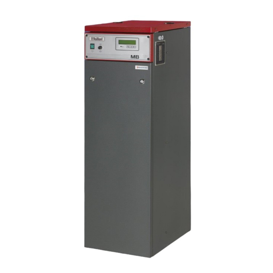
- Page 1 Installation - operating - servicing MB – boilers 35 – 45 – 60 – 75 – 90 105 - 120 - 140 -150kW...
-
Page 2: Technical Data
Pressure drop(Wc) Water speed(m/s) 0,11 0,14 0,19 0,23 0,28 Max. working pressure 6bar 6bar 6bar 6bar 6bar Min. working pressure 1bar 1bar 1bar 1bar 1bar Dimensions size (cm) Height Width Depth Weight empty, (kg) Varmeteknikk AS August 2017 e-mail: post@varmeteknikk.no... - Page 3 Water circulation Δt=20 °C (m³/h) Pressure drop(Wc) Water speed(m/s) 0,33 0,37 0,43 0,47 Max. working pressure 6bar 6bar 6bar 6bar Min. working pressure 1bar 1bar 1bar 1bar Dimensions(cm) Height Width Depth Weight empty, (kg) Varmeteknikk AS August 2017 e-mail: post@varmeteknikk.no...
- Page 4 MB 35 - 150kW 1. Temp. controller 2. Safety temp .limiter 3. ON/OFF –switch 4. Contactors 5. Fuses/circuit breakers 6. Bus bars for connecting Supply cables 7. Drain 8. Return 9. Flow 10. Expansion NB! Fri høyde over kjel, ca. 100cm Varmeteknikk AS August 2017 e-mail: post@varmeteknikk.no...
- Page 5 Additional functions Remote control Boiler Start/stop Temperature control Power control Monitoring Operation signal Failure signal Output signals 0-10V Terminal block Menus Maintenance Troubleshooting Circuit diagrams Control circuit Power circuit Temp. controller Terminals Spare parts Varmeteknikk AS August 2017 e-mail: post@varmeteknikk.no...
-
Page 6: Pressure Safety Valve
Two earth clamps is located in bottom of the switch gear for earth cables. Control voltage 220-230V control voltage is required. Connection to be done on F1 & F2 on the terminal block inside the boiler. See page 11. Varmeteknikk AS August 2017 e-mail: post@varmeteknikk.no... -
Page 7: Temperature Controller
1 °C. 3 relays control the power contactors which are connected in a binary order. This gives a high degree of reliability If a failure occurs, an alarm diode starts flashing. Type of failure will be shown in display and could Varmeteknikk AS August 2017 e-mail: post@varmeteknikk.no... -
Page 8: Settings
With +/- button choose desired step time. Press E button to save new value. Step 0( 7) Step lim 0( 7) ► Step time Step time Step lim 0( 7) Step 0( 7) ► Step time Step time To return to temp/power mode, press menu button. Varmeteknikk AS August 2017 e-mail: post@varmeteknikk.no... -
Page 9: Additional Functions
Temperature in brackets is calculated flow temperature depending on outdoor temperature. It is not possible to change calculated temperature when outdoor sensor is connected. Outdoor t. 24°C Parallel 0°C For further information, contact Varmeteknikk. Varmeteknikk AS August 2017 e-mail: post@varmeteknikk.no... -
Page 10: Temperature Control
12. "Power IN" must be set in "ON" position. Press + button twice and then E to enter new value. Power IN Press menu button twice to return to "Temp/Power" mode. When signal is activated display shows: StepE 3 ( 7) Step time Varmeteknikk AS August 2017 e-mail: post@varmeteknikk.no... -
Page 11: Terminal Block
External preset temperature: 0V = 20 °C, 10V = 120°C (terminal 36 & 37) Connection diagram, see page 17. Terminal block inside boiler Styrespenning Control voltage 230V 50Hz, 10A Inn-/utkobling On/off ext. Driftsignal Operation Feilsignal Failure Trafo Transformer Varmeteknikk AS August 2017 e-mail: post@varmeteknikk.no... -
Page 12: Menus
Test contactor K1-4 0000 Settings in main menu: Step time - Desired temperature Service 0 - Number of power steps - Step time Power IN Temp IN English Node 0 Net 107 Varmeteknikk AS August 2017 e-mail: post@varmeteknikk.no... -
Page 13: Maintenance
AF40, AF52, AF 65 Tightening torques for circuit breakers: type Connection screw Tightening torque MS132/10 M3,5 1,2Nm MS132/12 - 16 1,5Nm MS132/20 - 32 Tightening torque for heating element: M4 - 1,2Nm M12 - 15Nm Varmeteknikk AS August 2017 e-mail: post@varmeteknikk.no... -
Page 14: Troubleshooting
Check contactors and (Display shows Burned contactor replace if required "Alarm Power") Loose screws for heating element Tighten screws Gasket for heating element Replace if required LEAKAGE Defect heating element Replace if required Varmeteknikk AS August 2017 e-mail: post@varmeteknikk.no... - Page 15 Circuit diagram MB 35 - 150kW Varmeteknikk AS August 2017 e-mail: post@varmeteknikk.no...
-
Page 16: Power Circuit
Power circuit MB 35-150kW MB 35kW/45kW 400V Apparatplate Switch gear MB 60kW/75kW/90kW 400V Apparatplate Switch gear MB 105kW/120kW/140kW 400V Apparatplate Switch gear MB 150kW 400V Apparatplate Switch gear Varmeteknikk AS August 2017 e-mail: post@varmeteknikk.no... -
Page 17: Temp. Controller Terminals
Temp.controller, terminals Varmeteknikk AS August 2017 e-mail: post@varmeteknikk.no... -
Page 19: Spare Parts
Spare parts MB 35 – 150kW Number Item Article no. 35kW 45kW 60kW 75kW 90kW 105kW 120kW 140kW 150kW Heating element 6613 0001-K Heating element 6613 0001-P Heating element 7,5kW 6613 0001-AR Heating element 6613 0001-N Heating element 10kW 6672 0242-A... - Page 21 Notes Varmeteknikk AS August 2017 e-mail: post@varmeteknikk.no...
Need help?
Do you have a question about the MB 35 and is the answer not in the manual?
Questions and answers