Table of Contents
Advertisement
Advertisement
Table of Contents

Summary of Contents for Next Victor NM-II 3.2KW 24V PF1
- Page 1 User Manual 3KW / 5KW INVERTER / MPPT SCC / AC CHARGER Version: 1.8...
- Page 2 Table Of Contents ABOUT THIS MANUAL ............................. 1 Purpose ................................1 Scope ................................1 SAFETY INSTRUCTIONS ..........................1 INTRODUCTION ............................... 2 Features ................................2 Basic System Architecture ..........................2 Product Overview ............................. 3 INSTALLATION ..............................4 Unpacking and Inspection..........................4 Preparation ..............................
-
Page 3: About This Manual
ABOUT THIS MANUAL Purpose This manual describes the assembly, installation, operation and troubleshooting of this unit. Please read this manual carefully before installations and operations. Keep this manual for future reference. Scope This manual provides safety and installation guidelines as well as information on tools and wiring. SAFETY INSTRUCTIONS WARNING: This chapter contains important safety and operating instructions. -
Page 4: Introduction
INTRODUCTION This is a multi-function inverter/charger, combining functions of inverter, solar charger and battery charger to offer uninterruptible power support with portable size. Its comprehensive LCD display offers user-configurable and easy-accessible button operation such as battery charging current, AC/solar charger priority, and acceptable input voltage based on different applications. -
Page 5: Product Overview
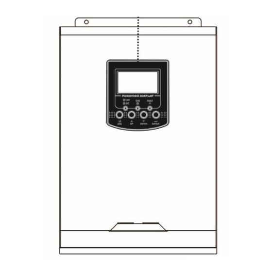
Product Overview 3KW/ 5KW side view 3KW/ 5KW model 1. LCD display 2. Status indicator 3. Charging indicator 4. Fault indicator 5. Function buttons 6. Power on/off switch 7. AC input 8. AC output 9. PV input 10. Battery input 11. -
Page 6: Installation
INSTALLATION Unpacking and Inspection Before installation, please inspect the unit. Be sure that nothing inside the package is damaged. You should have received the following items inside of package: The unit x 1 User manual x 1 Communication cable x 1 ... -
Page 7: Battery Connection
Install the unit by screwing two screws. It’s recommended to use M4 or M5 screws. Battery Connection CAUTION: For safety operation and regulation compliance, it’s requested to install a separate DC over-current protector or disconnect device between battery and inverter. It may not be requested to have a disconnect device in some applications, however, it’s still requested to have over-current protection installed. - Page 8 4. Connect all battery packs as below chart. It’s suggested to connect at least 100Ah capacity battery for 3KW model and at least 200Ah capacity battery for 5KW model . 5. Insert the battery wires flatly into battery connectors of inverter and make sure the bolts are tightened with torque of 2 Nm in clockwise direction.
-
Page 9: Ac Input/Output Connection
WARNING: Shock Hazard Installation must be performed with care due to high battery voltage in series. CAUTION!! Before making the final DC connection or closing DC breaker/disconnector, be sure positive (+) must be connected to positive (+) and negative (-) must be connected to negative (-). - Page 10 WARNING: Be sure that AC power source is disconnected before attempting to hardwire it to the unit. 4. Then, insert AC output wires according to polarities indicated on terminal block and tighten terminal screws. Be sure to connect PE protective conductor ( ) first.
-
Page 11: Pv Connection
PV Connection CAUTION: Before connecting to PV modules, please install separately a DC circuit breaker between inverter and PV modules. WARNING! It's very important for system safety and efficient operation to use appropriate cable for PV module connection. To reduce risk of injury, please use the proper recommended cable size as below. Model Wire Size Cable (mm... -
Page 12: Final Assembly
5. To ensure wires are securely connected, you fix wires to the strain relief with cable tie. Final Assembly After connecting all wirings, please put bottom cover back by screwing two screws as shown below. Communication Connection Please use supplied communication cable to connect to inverter and PC. Insert bundled CD into a computer and follow on-screen instruction to install the monitoring software. -
Page 13: Operation
Fault occurs in the inverter. Flashing Warning condition occurs in the inverter. Function Keys Function Key Description To exit setting mode To go to previous selection DOWN To go to next selection ENTER To confirm the selection in setting mode or enter setting mode... -
Page 14: Lcd Display Icons
LCD Display Icons Icon Function description Input Source Information Indicates the AC input. Indicates the PV input Indicate input voltage, input frequency, PV voltage, charger current (if PV in charging for 3K models), charger power (only for MPPT models), battery voltage. - Page 15 In battery mode, it will present battery capacity. Load Percentage Battery Voltage LCD Display < 1.85V/cell 1.85V/cell ~ 1.933V/cell Load >50% 1.933V/cell ~ 2.017V/cell > 2.017V/cell < 1.892V/cell 1.892V/cell ~ 1.975V/cell Load < 50% 1.975V/cell ~ 2.058V/cell > 2.058V/cell Load Information Indicates overload.
-
Page 16: Lcd Setting
LCD Setting After pressing and holding ENTER button for 3 seconds, the unit will enter setting mode. Press “UP” or “DOWN” button to select setting programs. And then, press “ENTER” button to confirm the selection or ESC button to exit. Setting Programs: Program Description... - Page 17 Available options in 3KVA model: 40A (default for MPPT model) 50A (default for PWM model) 70A (only for PWM model) Maximum charging Available options in 3KW/ 5KW model: current: To configure total charging current for solar and utility chargers. (Max. charging current = utility charging current + solar charging current)
- Page 18 Restart disable Restart enable Auto restart when overload occurs (default) Restart disable Restart enable Auto restart when over temperature occurs (default) 50Hz (default) 60Hz Output frequency Available options in 1KVA/2KVA model: 20A (default) Available options in 3KVA model: 25A (default) Maximum utility charging current Available options in 3KW/ 5KW model:...
- Page 19 Available options in 2KVA/3KVA/3KW model: 22.0V 22.5V 23.0V (default) 23.5V 24.0V 24.5V 25.0V 25.5V Setting voltage point back to utility source when selecting “SBU Available options in 5KW model: priority” or “Solar first” in program 01. 46V (default) Available options in 1KVA model: Battery fully charged 12.0V Setting voltage point...
- Page 20 13.3V 13.5V (default) 13.8V 14.0V 14.3V 14.5V Available options in 2KVA/3KVA/3KVA Plus model: Battery fully charged 24.5V Setting voltage point 25.5V back to battery mode when selecting “SBU priority” or “Solar first” in program 01. 26.5V 27V (default) 27.5V 28.5V Available options in 5KVA model: Battery fully charged...
- Page 21 54V (default) Setting voltage point back to battery mode when selecting “SBU priority” or “Solar first” in program 01. If this inverter/charger is working in Line, Standby or Fault mode, charger source can be programmed as below: Solar first Solar energy will charge battery as first priority.
- Page 22 Backlight on (default) Backlight off Backlight control Alarm on (default) Alarm off Beeps while primary source is interrupted Overload bypass: Bypass disable (default) Bypass enable When enabled, the unit will transfer to line mode if overload occurs in battery mode. Record enable (default) Record disable Record Fault code...
- Page 23 1KW default setting: 10.5V 3KW default setting: 21.0V Low DC cut-off voltage 5KW default setting: 42.0V If self-defined is selected in program 5, this program can be set up. Setting range is from 10.5V to 12.0V for 1K model, 21.0V to 24.0V for 3KW model and 42.0V to 48.0V for 5KW model .
-
Page 24: Display Setting
LCD main page will shows “ ”. If “Disable” is selected, it will cancel equalization function until next activated equalization time arrives based on program 35 setting. At this time, “ ” will not be shown in LCD main page. - Page 25 MPPT charging power=500W Charging power (only for MPPT model) Battery voltage=25.5V, output voltage=230V Battery voltage and output voltage Output frequency=50Hz Output frequency Load percent=70% Load percentage When connected load is lower than 1kVA, load in VA will present xxxVA like below chart. Load in VA When load is larger than 1kVA (≧1KVA), load in VA will present x.xkVA like below chart.
- Page 26 When load is lower than 1kW, load in W will present xxxW like below chart. Load in Watt When load is larger than 1kW (≧1KW), load in W will present x.xkW like below chart. Battery voltage=25.5V, discharging current=1A Battery voltage/DC discharging current Main CPU version 00014.04 Main CPU version checking Secondary CPU version 00003.03...
-
Page 27: Operating Mode Description
Operating Mode Description Operation mode Description LCD display Charging by utility and PV energy. Standby mode / Power saving mode Charging by utility. Note: *Standby mode: The inverter is No output is supplied by the not turned on yet but at this unit but it still can charge time, the inverter can charge batteries. - Page 28 Operation mode Description LCD display Charging by utility and PV energy. The unit will provide output power from the mains. It will Line Mode also charge the battery at Charging by utility. line mode. Power from battery and PV energy. The unit will provide output Battery Mode power from battery and PV...
- Page 29 Battery Equalization Description Equalization function is added into charge controller. It reverses the buildup of negative chemical effects like stratification, a condition where acid concentration is greater at the bottom of the battery than at the top. Equalization also helps to remove sulfate crystals that might have built up on the plates. If left unchecked, this condition, called sulfation, will reduce the overall capacity of the battery.
- Page 30 However, in Equalize stage, when battery equalized time is expired and battery voltage doesn’t rise to battery equalization voltage point, the charge controller will extend the battery equalized time until battery voltage achieves battery equalization voltage. If battery voltage is still lower than battery equalization voltage when battery equalized timeout setting is over, the charge controller will stop equalization and return to float stage.
-
Page 31: Fault Reference Code
Fault Reference Code Fault Code Fault Event Icon on Fan is locked when inverter is off. Over temperature Battery voltage is too high Battery voltage is too low Output short circuited or over temperature is detected by internal converter components. Output voltage is too high Overload time out Bus voltage is too high... -
Page 32: Specifications
SPECIFICATIONS Table 1 Line Mode Specifications INVERTER MODEL Input Voltage Waveform Sinusoidal (utility or generator) Nominal Input Voltage 230Vac 170Vac± 7V (UPS); Low Loss Voltage 90Vac± 7V (Appliances) 180Vac± 7V (UPS); Low Loss Return Voltage 100Vac± 7V (Appliances) High Loss Voltage 280Vac±... -
Page 33: Table 2 Inverter Mode Specifications
Table 2 Inverter Mode Specifications INVERTER MODEL Rated Output Power 3KVA/3KW 5KVA/5KW Pure Sine Wave Output Voltage Waveform 230Vac± 5% Output Voltage Regulation 50Hz Output Frequency Peak Efficiency Overload Protection 5s@≥150% load; 10s@110%~150% load 2* rated power for 5 seconds Surge Capacity Nominal DC Input Voltage 24Vdc... -
Page 34: Table 3 Charge Mode Specifications
Table 3 Charge Mode Specifications Utility Charging Mode INVERTER MODEL Charging Algorithm 3-Step AC Charging Current (Max) 60Amp (@V =230Vac) Bulk Charging Flooded Battery 29.2 58.4 Voltage AGM / Gel Battery 28.2 56.4 Floating Charging Voltage 27Vdc 54Vdc Battery Voltage, per cell Charging Current, % 2.43Vdc (2.35Vdc) Voltage... -
Page 35: Trouble Shooting
TROUBLE SHOOTING Problem LCD/LED/Buzzer Explanation / Possible cause What to do Unit shuts down LCD/LEDs and buzzer automatically will be active for 3 The battery voltage is too low 1. Re-charge battery. during startup seconds and then (<1.91V/Cell) 2. Replace battery. process. -
Page 36: Appendix: Approximate Back-Up Time Table
Appendix: Approximate Back-up Time Table Model Load (VA) Backup Time @ 24Vdc 100Ah (min) Backup Time @ 24Vdc 200Ah (min) 1100 1200 1500 1800 2100 2400 2700 3000 Model Load (VA) Backup Time @ 48Vdc 100Ah (min) Backup Time @ 48Vdc 200Ah (min) 1288 1000 1500...
Need help?
Do you have a question about the Victor NM-II 3.2KW 24V PF1 and is the answer not in the manual?
Questions and answers
victor mnl 3200-24V ( U1.0 (27) 009 ) error How can I solute it