Table of Contents
Advertisement
Advertisement
Table of Contents

Summary of Contents for Pelegrin Tarragon
- Page 1 Pilot's Operating Handbook and Flight Manual YL-MFG Pelegrin LIMITED LIABILITY COMPANY Identification No. 50103508691 VAT No. LV50103508691 Rigas gatve 8, Adazi, Adazi region, LV-2123 Latvia info@pelegrin.lv Pilots Operating Handbook YL-MFG 1/76 Revision 7, Issue 1 6-Apr-16...
-
Page 2: List Of Effective Pages (Lep)
0 List of Effective Pages (LEP) This is Revision 6 of the Pilots Operating Handbook for YL-MFG. Use the following table to determine the effective pages with revisions. Chapter Page Nr. Revision Date 22.10.2015 22.10.2015 23.11.2015 28.05.2015 23.11.2015 22.10.2015 23.11.2015 1.10.2015 10.10.2015 9-14... -
Page 3: Table Of Contents
Table of Contents LIST OF EFFECTIVE PAGES (LEP) GENERAL NTRODUCTION ASIC ESCRIPTION NGINE AND ROPELLER 1.3.1 NGINE 1.3.2 ROPELLER IEW AND IMENSIONS OPERATING LIMITATIONS AXIMUM EIGHTS EIGHT IMITATION ABLE (IAS) IRSPEEDS AND IMITATIONS 2.3.1 IRSPEED NDICATOR ARKINGS ANEUVERING OAD ACTORS ENTER OF RAVITY ANGE PPROVED ANEUVERS PECIFIC PERATION IMITS NGINE 2.10 NGINE AND... - Page 4 3.4.2 26-26 ORCED ANDINGS 3.4.3 BRS 27-28 ANDING WITH 3.4.4 ANDING WITHOUT LEVATOR ONTROL 3.4.5 IRES 3.4.6 PINS 3.4.7 PARK LUG OULING NORMAL PROCEDURES NTRODUCTION (IAS) IRSPEEDS FOR ORMAL PERATION 31-34 REFLIGHT NSPECTION 34-35 UEL ILLING NGINE TART AXI HECK AKEOFF LIGHT 38-39 ANDING PERFORMANCE TALL PEEDS...
- Page 5 7.5.4 ONTROL TICK 7.5.5 HROTTLE AND RAKE ONTROL EVERS 7.5.6 AMERAS 7.5.7 QUIPMENT WITCH ANEL 7.5.8 QUIPMENT WITCH ANEL 7.5.9 IRCUIT BREAKER PANEL 7.5.10 YNON KYVIEW VIONICS ITOT ROUND ANEUVERING ANDING AGGAGE 7.10 EATS EAT ELT AND HOULDER ARNESS 7.10.1 EATS 7.10.2 EAT ELTS 7.10.3 PILOT SEAT 7.11...
- Page 6 71-72 EIGHT AND ALANCE ERMINOLOGY LECTRICAL AND VIONICS ERMINOLOGY /U.S. ETRIC MPERIAL ONVERSION HARTS ENGTH ONVERSIONS ISTANCE ONVERSIONS EMPERATURE ONVERSIONS RESSURE ONVERSIONS UEL OLUME EIGHT ONVERSIONS IST OF ANUALS www.tarragonaircraft.com The airplane must be operated according to information and limitations, which are presented in this handbook This handbook must be available to the pilot at any time during the flight...
-
Page 7: General
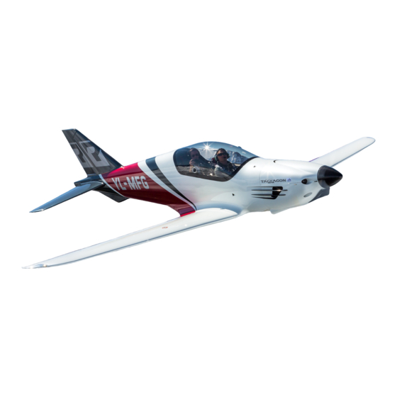
The Tarragon is an all-carbon-composite, tandem-seat, low-wing Aircraft, designed to set new standards for safety, weight and performance. The Tarragon has been designed and calculated ground-up by C.F.M. Air, in Turino, an Italian Aerospace Design Company, under the guidance of Maurizio Cheli, former Astronaut and chief test pilot for ALENIA. -
Page 8: E Ngine And P Ropeller
Engine and Propeller 1.3.1 Engine Engine Manufacturer: EPA Power SrL, 28012 Cressa - Italy Engine Model: SA-R917Ti Displacement: 1355 cm Maximum Power (5700 rpm): 100 kW/135 hp Maximum continuous (5500 rpm): 82 kW/110 hp EPA Power SA-R917Ti is based on the the Rotax 914 engine, it is a horizontally opposed 4-cylinder engine with pushrod actuated OHV, 2 valves per cylinder,... -
Page 9: View And Dimension (Mm)
3 View and Dimensions (mm) Pilots Operating Handbook YL-MFG 9/76 Revision 7, Issue 1 4/6/2016... -
Page 10: Operating Limitations
2 Operating Limitations Maximum Weights (kg) Takeoff Landing Max. weight in baggage compartment Standard empty weight Maximum useful load Wing loading 70,1 kg/sq. Power Loading 5,0 kg/HP Weight Limitation Table (kg) MTOW Empty weight Fuel kg (L /0.7) Max. crew weight No baggage. -
Page 11: A Irspeed I Ndicator M Arkings
2.3.1 Airspeed Indicator Markings MARKING SIGNIFICANCE value or range Red Band <46 Low airspeed warning. White Band 46 – 74 Full flap operating range. Lower limit is maximum weight V in landing configuration. Upper limit is maximum speed permissible with flaps extended. Green Band 54 –... -
Page 12: Center Of Gravity Range
Specific Operation Limits The Tarragon airplane is approved for DAY - VFR operations only. Flight into known icing conditions is prohibited. Operating Rules as defined by local authorities must be adhered to. WARNING: Only VFR day flights are permitted. -
Page 13: Fuel
Fuel Approved fuel grades are Mogas (min. RON 95) or AVGAS 100 LL. Recommended fuel for Rotax type 912 and 914 engines is Mogas RON 98. Note: Due to the higher lead content in AVGAS, the wear of the valve seats, the deposits in combustion chamber and lead sediments in the lubrication system will increase. - Page 14 Operation outside temperature range - 25°C/+ 50°C CAUTION: Engine operation with indicated oil pressure below the green band ranges while in cruise or climb configuration is considered abnormal. Refer to section 3, amplified emergency procedures, „low oil pressure “. Pilots Operating Handbook YL-MFG 14/76 Revision 7, Issue 1...
-
Page 15: E Ngine And I Nstrument M Arkings
2.10 Engine and Instrument Markings Power plant and electrical instrument markings and their color code significance are shown in figure below. Operation with indications in the red range is prohibited. Avoid operating with indicators in the yellow range. INSTR. YELLOW GREEN YELLOW Tachometer (RPM) -
Page 16: Emergency Procedures
3 Emergency Procedures Introduction Section 3 provides checklist and amplified procedures for coping with emergencies that may occur. Emergencies caused by airplane or engine malfunctions are extremely rare if proper preflight inspections and maintenance are practiced. En route weather emergencies can be minimized or eliminated by careful flight planning and good judgment when unexpected weather is encountered. -
Page 17: F Orced L Andings
ENGINE FAILURE IMMEDIATELY AFTER TAKEOFF Airspeed – 62 Kts (115 km/h) IAS FUEL SHUTOFF Valve - OFF IGNITION Switch - OFF LDG GEAR - DOWN (if not already down) Wing Flaps - AS REQUIRED (FULL recommended) MASTER Switch - OFF (when flaps are set and landing is assured) Land - STRAIGHT AHEAD Canopy Latch - OPEN (just prior to touchdown) ENGINE FAILURE DURING FLIGHT (Restart Procedures) - Page 18 PRECAUTIONARY LANDING WITH ENGINE POWER Seat Belts - SECURE Airspeed – 62 Kts (115 km/h) IAS LDG GEAR - DOWN Wing Flaps - 10° or 20° Radio - ALERT ATC or TRANSMIT MAYDAY ON 121.5 MHZ, (give location, intentions and SQUAWK 7700) Selected Field - FLY OVER (noting terrain and obstructions) Wing Flaps - FULL (on final approach)
-
Page 19: Fire
OTHER THAN IMMINENT CRASH SITUATIONS Radio - TRANSMIT MAYDAY on 121.5 MHz, (give location, intentions and SQUAWK 7700) Heavy Objects (in baggage area) - SECURE (if possible) Seat Belts - SECURE THROTTLE - IDLE SPEED – 62 Kts (115 km/h) IAS or less IGNITION Switch - OFF ELT - ACTIVATE BRS - ACTIVATE, PULL HANDLE OUT... - Page 20 FUEL SHUTOFF Valve - OFF (pull full out) THROTTLE - FULL or FAST CRUISE setting Airspeed – 81 Kts (150 km/h) IAS (If fire is not extinguished, increase glide speed to find an airspeed, within airspeed limitations, which will provide an incombustible mixture) Cabin Vents - OPEN (as needed) CABIN HEAT Control Knob - OFF (push full in) (to avoid drafts) Forced Landing - EXECUTE (refer to EMERGENCY LANDING WITHOUT ENGINE POWER)
- Page 21 INADVERTENT ICING ENCOUNTER DURING FLIGHT WARNING: Use emergency landing with BRS activation whenever crash is imminent. 1. Turn back or change altitude to exit icing conditions. Consider lateral or vertical flight path reversal to return to last „known good“ flight conditions (to obtain an outside air temperature that is less conducive to icing).
-
Page 22: L Anding G Ear M Alfunctions
3.3.5 Landing Gear Malfunctions LANDING GEAR RETRACTION FAULT LDG GEAR Circuit Breaker - TRIP (OUT/OFF) CLIMB TO SAFE ALTITUDE SPEED – 65 Kts (120 km/h) IAS OR BELOW LDG GEAR Circuit Breaker - CHECK IN LDG GEAR Switch - DOWN GEAR Indication - CHECK DOWN (IF NOT DOWN, refer to LDG GEAR EXTENSION FAULT) LAND as soon as practicable SPEED LIMIT –... -
Page 23: C Anopy Open In Flight
LANDING WITH A FLAT / PARTIALLY OPENED / UNLOCKED NOSE WHEEL 1. Approach - NORMAL (choose longest runway if possible) 2. Wing Flaps - AS REQUIRED 3. Touchdown - ON MAINS (tail slightly low) 4. Elevator - continue stick to full aft as airplane slows (hold nose wheel off the ground as long as Possible) 5. -
Page 24: E Lectrical P Ower S Upply S Ystem M Alfunctions
3.3.8 Electrical Power Supply System Malfunctions LOSS OF ALL ELECTRICAL POWER (EXCEPT PFD) 1. MAIN CB RESET Switch - PRESS MOMENTARILY IF ELECTRICAL POWER RESUMES NORMAL OPERATION 2. Continue flight and land as soon as practical. IF ELECTRICAL POWER REMAINS INOPERATIVE (EXCEPT PFD) 3. - Page 25 VOLTS INDICATION ABOVE GREEN BAND RANGE OR VOLTS MORE THAN 15 1. Electrical Load - REDUCE as follows: a. LDG Light Switch - OFF (use as required for landing) b. NAV Light Switch - OFF c. STROBE Light Switch - OFF d.
-
Page 26: A Mplified E Mergency P Rocedures
Amplified Emergency Procedures The following Amplified Emergency Procedures provide additional information beyond that in the Emergency Procedures Checklists portion of this section. These procedures also include information not readily adaptable to a checklist format, and material to which a pilot could not be expected to refer in resolution of a specific emergency. - Page 27 The more this impact is reduced, the more height is needed to open the chute. The BRS used in Tarragon is designed for speeds up to 350 km/h. The minimal height of use with this system is 180–240 ft. (60-80m) and the stress on opening can be 3.5 – 5.5 G.
- Page 28 maneuver is relatively near to the ground, the GRS may provide the life-saving back up the pilot requires. Pilot incapacitation This may include situations such as a heart attack, stroke, being temporarily blinded, extreme levels of stress where a pilot “freezes up” and cannot act properly. In this case a passenger must activate the GRS.
- Page 29 smell of burning insulation. The checklist procedure for electrical fires calls for electrical power to be turned off. All flight instruments and navigation will be lost at this time. The checklist procedure should result in the elimination of the fire. When the fire is extinguished, electrical power may be turned on to those systems not involved.
-
Page 30: Normal Procedures
4 Normal Procedures Introduction Section 4 provides procedures for normal operations using standard and optional equipment. Unless otherwise noted, the following speeds are based on a maximum weight of 660 kg and may be used for any lesser weight. Airspeeds for Normal Operation (IAS) km/h Takeoff Normal Climb... - Page 31 Preflight Inspection NOTE: Visually check the airplane for general condition during walk-around inspection. Airplane should be parked in a normal ground attitude to make sure that three drain valves allow for accurate sampling. In cold weather, remove even small accumulations of frost, ice or snow from wing, tail and control surfaces.
- Page 32 (1) CABIN Pilot's Operating Handbook - AS DESIRED MFD Pilot’s Guide - AS DESIRED Pilot’s Checklist - ACCESSIBLE TO PILOT Throttle Lever - CHECK (free movement) Parking Brake - SET GRS Activation Handle (if installed) - CHECK a. Handle Mount - CHECK (security and condition) b.
- Page 33 Fuel Filler Cap - SECURE Pitot Tube Cover - REMOVE (check for pitot blockage) 10. Strobe/Nav/Landing Light - CHECK (condition, operation and cleanliness of cover) WARNING: Takeoff is prohibited with less than ¼ tank of fuel. (3) LEFT WING Trailing Edge 1.
- Page 34 WARNING: Takeoff is prohibited with less than ¼ tank of fuel. Drain at least a cupful of fuel (using sampler cup) from each sump location to check for water, sediment, and proper fuel grade before each flight and after each refueling. If water is observed, take further samples until clear and then gently rock wings and lower tail to the ground to move any additional contaminants to the sampling points.
- Page 35 To fill the tanks full, fill until fuel touches the bottom part of filler cap flange in one tank, then fill the second tank. Let it sit for a few minutes, so that the fuel finds its way in the sponge and levels out in both tanks and top up both tanks.
- Page 36 Engine Start BEFORE ENGINE START 1. Preflight Inspection - COMPLETE 2. Passenger Briefing - COMPLETE 3. Seat Belts - ADJUST and SECURE 4. Canopy - Close 5. Brakes - TEST and SET 6. Circuit Breakers - CHECK IN 7. Electrical Equipment - OFF 8.
- Page 37 Takeoff BEFORE TAKEOFF Parking Brake - SET Brakes - APPLY PARKING BRAKE Control Lever - ON (pull) Seat Belts - ADJUST and SECURE Canopy lock - CHECK Flight Controls - FREE and CORRECT Flight Instruments (PFD) - CHECK (verify no faults) Engine Monitoring System - CHECK PARAMETERS (verify no faults) Altimeter - SET Fuel Quantity Indicators - CHECK (verify level is correct)
- Page 38 In Flight EN ROUTE CLIMB Airspeed – 76-86 Kts (140-160 km/h) IAS THROTTLE/PROP Control - Cruise Setting NOTE: For maximum performance climb speeds, refer to Section 5, Maximum Rate of Climb. CRUISE Economy cruise setting (57%): THROTTLE Control - MAP 27.5 in Hg PROP (if applicable) - 5100 RPM Elevator Trim Control Switch - ADJUST if necessary Fast cruise setting (75%):...
- Page 39 SHORT FIELD LANDING Airspeed – below 70 Kts (130 km/h) IAS (Flaps UP) LDG GEAR - DOWN Wing Flaps - FULL Airspeed – 54 Kts (100 km/h) IAS (until flare) NOTE: When performing a short field landing approach, pilot should monitor airspeed closely and be prepared to initiate stall avoidance procedures.
- Page 40 All performance figures are based on airplane weight of 660 kg, standard atmospheric conditions, level, hard-surfaced dry runways and no wind. They are estimated values derived from flight tests conducted by Pelegrin Ltd. under carefully documented conditions and will vary with individual airplanes and numerous factors affecting flight performance.
- Page 41 Engine Performance (at standard temperatures and pressures) Setting Engine RPM Power (hp) Torque (Nm) MAP (inHg) TPS (%) Take-off 5700 Max. 5500 Continuous 75 % 5000 65 % 4800 55 % 4300 Landing Distance (m) Distances stated are valid at sea level and MTOW 660 kg. Landing distance over Flaps position 3 (35°) Landing run...
- Page 42 5.7.2 Climb test At the time of the climb test the airplane was at 625 kg take off weight and the test was performed at Vy=90 Kts IAS: Minutes Press Alt 2000 5500 3500 5500 4300 5500 5300 5500 6300 5500 7350 5500...
-
Page 43: Weight And Balance
6 Weight and Balance Introduction This section describes the procedure for establishing the basic empty weight and moment of the airplane. Sample forms are provided for reference. Procedures for calculating the weight and moment for various operations are also provided. WARNING: It is the responsibility of the pilot to make sure the airplane is loaded properly. - Page 44 The Basic Empty CG Arm is 3.520 meters from datum or 9.9% of MAC. Weight and Balance Tables The following information will enable you to operate your Tarragon within the prescribed weight and center of gravity limitations. To determine weight and balance, use the Sample Loading Table, as...
- Page 45 Loading Table 1 (Sample Problem with Very FWD CG) ITEM DESCRIPTION WEIGHT CG ARM MOMENT 1 Basic empty weight 3.515 1418.88 2 Fuel (@ 0.72 kg/l) - Standard fuel 85l max. 3.492 223.49 - Reduced fuel, e.g., 60l 3.492 3 Pilot 3.488 331.36 4 Passenger...
- Page 46 Loading Table 3 (Sample Problem for YL-MFG, Estimates) ITEM DESCRIPTION WEIGHT CG ARM MOMENT 1 Basic empty weight 3.515 1418.88 2 Fuel (@ 0.72 kg/l) - Standard fuel 85l max. 3.492 - Reduced fuel, e.g., 42l 3.492 104.70 3 Pilot 3.488 279.04 4 Passenger...
- Page 47 7 Airplane and Systems Description Introduction This section provides description and operation of the airplane and its systems. Refer to Addendum/Manuals for details on optional systems and equipment. Airframe The airplane is an all-composite, two-place, low wing; single-engine airplane equipped with retractable tricycle landing gear and is designed for sport flying and introductory training purposes.
- Page 48 Dual control sticks are used for aileron and elevator control. The control stick location is designed so that the pilot's right hand naturally falls on the control stick. The rudder is held centered by the springs used for increasing rudder pedal force. Pilots Operating Handbook YL-MFG 48/76...
- Page 49 Pilots Operating Handbook YL-MFG 49/76 Revision 7, Issue 1 4/6/2016...
- Page 50 Rudder pedals provide rudder control through pilot and copilot pedal assemblies. An elevator trim tab is located on the left elevator. Trim tab operation is by direct linkage to an elevator mounted electric servo motor controlled by a control stick mounted electric trim switch. Sliding the trim switch up to the TRIM DN position will bring the nose of the airplane down while sliding the trim switch down to the TRIM UP position will trim the nose of the airplane up.
- Page 51 Instrument Panel, Flight and Systems Instruments 7.5.1 Front Cockpit (Pilot) The Tarragon is piloted from the front cockpit. All systems necessary for engine/propeller control and management, flaps, gear lowering and communications controls are located in the front. The electrical system switch/circuit breaker panel,...
- Page 52 7.5.2 Rear Cockpit (Passenger) Engine controls, control stick, pedals, BRS handle and glass instrument screen are doubled in the rear cockpit. The EFIS and COM located in the front have remote heads in the back. The passenger can operate the COM separately. 7.5.3 Cockpit Layout Description 1.
- Page 53 7.5.4 Control Stick Control stick handle has an ergonomic design to improve comfort and controls. The control stick has different switches, consult the following picture and table for the functions: Push to Talk Trimm Adjustment TRIM Auto Pilot Frequency Flip Flip/Flop Camera Switch 7.5.5 Throttle and Brake Control Levers...
- Page 54 7.5.7 Equipment Switch Panel Equipment switches have a label on each switch describing the specific equipment it operates. 1 PUMP 2 – each switch operates 1 electric fuel pump • STROBE – operates the strobe lights • LIGHT – operates the navigation lights •...
- Page 55 7.5.9 Circuit breaker panel Circuit breaker panel has all the corresponding labels. The picture shows the circuit breaker current ratings: 7.5.10 Dynon Skyview Avionics This aircraft has all of the avionics and engine instrument systems integrated in Dynon Skyview. The front cockpit is equipped with a 10” Dynon Skyview touch display, and the rear cockpit has a redundant 7”...
- Page 56 The brake levers are located below the throttle levers and should be operated with the left hand together with the throttle. The Tarragon is equipped with single action hydraulic braking system with disc brakes on both main landing gear wheels. The brake levers, like throttle levers, are doubled for both pilots.
- Page 57 Landing Gear The tricycle type landing gear on the Tarragon features gas-hydraulic shock absorbers and electric retraction system. The nose wheel is steerable with directional control done via rudder pedals. This permits very tight turning and maneuvering in confined spaces.
- Page 58 Baggage Area The baggage area is accessed by a separate door on the side of the fuselage and is separated from both the cabin and the tail cone. Max. weight in baggage compartment is 20kg 7.10 Seats, Seat Belt and Shoulder Harness 7.10.1 Seats The seating arrangement consists of two crew seats in tandem configuration for the pilot and copilot.
- Page 59 7.12 Engine Controls Engine power is set using the throttle control. The throttle control is located on the left wall of the cockpit. The throttle control is configured so that the throttle is open in the forward position and closed in the full aft position. Engine fuel mixture, ignition and the waste gate are controlled automatically.
- Page 60 7.15 Ignition System The engine is equipped with a dual ignition unit of a breaker less, capacitor discharge design, with an integrated generator. The ignition unit needs no external power supply. Two independent charging coils (1) located on the generator stator supply one ignition circuit each. The energy is stored in capacitors of the electronic modules (2).
- Page 61 7.16 Cooling System The cooling system of the engine is designed for liquid cooling of the cylinder heads and ram-air cooling of the cylinders. The cooling system of the cylinder heads is a closed circuit with an expansion tank. The coolant flow is forced by a water pump, driven from the camshaft, from the radiator to the cylinder heads.
- Page 62 For the correct fuel pressure, refer to Operators Manual for EPA Power engine Type SA-R917Ti. The Following Picture shows a schematic of the fuel circuit for EPA SA-R917Ti Powered tarragon aircraft: Fuel Shutoff Valve...
- Page 63 7.17.1 Fuel Indication Fuel quantity is measured by two fuel level sensors located in each fuel tank. Fuel level indicators and fuel calculator is integrated in Dynon Skyview CAUTION: Never fully rely on fuel indicators for fuel levels. It is good practice to know the approximate amount of fuel added to and/or in the tanks, and to confirm the indicators are showing correctly.
- Page 64 7.18 Electrical Wiring Diagram Pilots Operating Handbook YL-MFG 64/76 Revision 7, Issue 1 4/6/2016...
- Page 65 7.19 Battery The battery is a Super B SB12V5200P-BC lightweight lithium ion starter battery based on lithium iron phosphate technology (LiFePO4). This lithium ion technology used in Super B batteries is the safest lithium ion technology available today. Technical data Nominal Voltage 13,2 End of Charge Voltage...
- Page 66 7.20 Ballistic Rescue System Galaxy GRS 6 600 Speedy FF 115 m Please refer to section 3.4.3. for general information on the use of BRS systems. The system installed in YL-MFG is made to work specifically at low heights and slow speeds. The parachute is pulled out by a specially designed rocket engine.
- Page 67 7.21 Engine Preheater The Reiff preheat system for Rotax 912 and 914 aircraft engines is an engine-mounted electric preheat system designed for easier cold-weather starts. The preheat system consists of a 100 W metal hot-strip element, which is epoxied to the bottom of the crankcase, and a 50 W band heater that is clamped to the oil tank.
- Page 68 8 Maintenance and Inspections A systematic approach to maintenance and inspections is the basis for a safe operation of the aircraft. The applied system consists of three elements: 1. Maintenance 2. Daily Inspection 3. Pre-/Post-Flight Inspection Maintenance Airframe, engine and systems maintenance is performed periodically, according to the respective requirements and rules, described in the maintenance manuals.
- Page 69 9 APPENDIX Symbols, Abbreviations and Terminology General Airspeed Terminology and Symbols CAS (Calibrated Airspeed): Indicated airspeed corrected for position and instrument error and expressed in km/h. Calibrated airspeed is equal to TAS in standard atmosphere at sea level. IAS (Indicated Airspeed): Speed shown on the airspeed indicator and expressed in km/h.
- Page 70 Meteorological Terminology OAT (Outside Air Temperature): Free air static temperature expressed in degrees Celsius. STD (Standard Temperature): Standard Temperature is 15°C at sea level pressure altitude and decreases by 2°C for each 1000 feet of altitude. PA (Pressure Altitude): Pressure Altitude is the altitude read from an altimeter when the altimeter's barometric scale has been set to 29.92 inches of mercury (1013 mb).
- Page 71 Quantity of fuel that cannot be safely used in flight. l/h (Liters Per Hour): Amount of fuel consumed per hour. m/s (Meters per Second): Distance in meters, traveled over the duration of one second. Acceleration due to gravity. T/O: Takeoff Weight and Balance Terminology Reference Datum: Imaginary vertical plane from which all horizontal distances are measured for balance purposes.
- Page 72 Maximum weight approved for ground maneuver, and includes the weight of fuel used for start, taxi and run-up. Maximum Takeoff Weight: Maximum weight approved for the start of the takeoff roll. Maximum Landing Weight: Maximum weight approved for the landing touchdown. Useful Load: Difference between ramp weight and the basic empty weight.
- Page 73 Metric/Imperial/U.S. Conversion Charts Length Conversions Pilots Operating Handbook YL-MFG 73/76 Revision 7, Issue 1 4/6/2016...
- Page 74 Distance Conversions Pilots Operating Handbook YL-MFG 74/76 Revision 7, Issue 1 4/6/2016...
- Page 75 Temperature Conversions Pressure Conversions Pilots Operating Handbook YL-MFG 75/76 Revision 7, Issue 1 4/6/2016...
- Page 76 Fuel Volume-To-Weight Conversions List of Manuals Maintenance Manual EPA Power Engine Manual Skyview Pilot’s User’s Guide Manual for EFIS/Autopilot Pilots Operating Handbook YL-MFG 76/76 Revision 7, Issue 1 4/6/2016...
Need help?
Do you have a question about the Tarragon and is the answer not in the manual?
Questions and answers