
Related Manuals for BRINKS ARRAY smart deadbolt

Summary of Contents for BRINKS ARRAY smart deadbolt
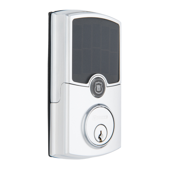
- Page 1 999-00451 Smart Deadbolt Secure control from anywhere. ™ Installation Instructions Simply Smart Security. ™...
- Page 2 Installation Instructions 999-00451 Box Contents Screw Cover Key (2) Exterior Gasket Interior Rechargeable Interior Mounting Assembly Assembly Battery Plate Drive-in Latch Collar Square Corner Strike Reinforcement Dust Box (Optional) Face Plate Plate Plate Mounting Screws (2) --------- Mounting Plate Screw (1) ------------------ USB Cable Interior Housing Screw (1) ------------------------- Battery Compartment Screws (2) ----------------------...
- Page 3 Tools you will need: Tools you may need: IMPORTANT INSTALLATION NOTES. PLEASE READ: • Remove the battery from the battery compartment and charge it in the Charging Cradle until the LED turns green. • The ARRAY lock has a built-in solar panel that will charge the battery if ™...
- Page 4 Installation Overview Part Description BATTERY COVER (L) Exterior Assembly Cylinder RECHARGEABLE Tailpiece BATTERY (J) Power Cable Gasket BATTERY COMPARTMENT Latch SCREWS (DD) Interior Mounting Plate Interior Assembly Rechargeable Battery Antenna Cover INTERIOR ASSEMBLY (I) Battery Cover Tailpiece Receiver Strike Plate ANTENNA Reinforcement Plate COVER (K)
- Page 5 Pre-Installation Instructions 1. Charge Battery a. Remove the Battery Cover (L), Rechargeable b. Carefully remove the Antenna Battery (J), Battery Charging Cradle, USB Cable Cover (K) by gently pulling the and Wall Adapter. Remove the plastic tab on the edges outward slightly and lifting. Battery (J).
- Page 6 4. Install Latch and Strike Plate (Continued) Determine the Proper Faceplate Mortise on door edge chiseled: Square corner faceplate Round corner faceplate Door edge not chiseled: Drive-in collar option Drive-in collar Set the Latch Backset The distance from the center of the bore hole to the edge of the door is called the backset. If the backset of your door is 2-3/8", you don’t need to adjust the latch.
- Page 7 Deadbolt Installation Instructions 5. Install Lock Assemblies Door Bore Hole Options Option 1 Option 2 For door with bore hole 2-1/8" diameter For door with bore hole 1-1/2" diameter follow Steps B proceed to STEP D. and C for Mounting Plate Screw (BB) and Mounting Plate removal.
- Page 8 5. Install Lock Assemblies (Continued) Power Cable (E) goes underneath the latch. Insert Bulged part of the Interior Mounting Plate (H) Tailpiece (D) horizontally. must be toward the door. EXTERIOR VIEW Door Power Cable (E) Tailpiece Tailpiece (D) Power Cable (E) Exterior Exterior Interior...
- Page 9 5. Install Lock Assemblies (Continued) J. Align the Tailpiece Receiver (M) of the Interior Assembly (I) into the Tailpiece (D). INTERIOR VIEW Interior Assembly (I) Interior Assembly (I) Power Cable (E) Tailpiece Receiver (M) Tailpiece (D) K. Insert the two Battery Compartment Screws (DD) and tighten.
- Page 10 Door Preparation Instructions for New Doors If installing ARRAY ™ on a new door, follow the door preparation instructions and use the template on Page 10. Mark Door with Template Mark the centerline for the deadbolt about 44" 5½" (1120 mm) from the floor, or about 5-1/2" (140 mm) 140mm above the center of an existing knob or lever.
- Page 11 TEMPLATE...
- Page 12 The temperature range for using the battery is -10°C to 60°C (14°F to 140°F). Use of the battery outside of this temperature range may damage the performance of the battery or may reduce its life expectancy. • Do not use the battery in any device except the BRINKS HOME SECURITY ARRAY Smart Deadbolt. ™...
Need help?
Do you have a question about the ARRAY smart deadbolt and is the answer not in the manual?
Questions and answers