Advertisement
Table of Contents
- 1 Introduction – Basic Description of PERIDECT
- 2 HW of the PERIDECT+ System
- 3 Standard Version
- 4 Antivandal Version
- 5 Hidden Version
- 6 CUP+ – Control Unit PERIDECT
- 7 Connecting the CUP+ Terminal Board
- 8 LCP+ – Line Controller PERIDECT
- 9 LED Signalling of CUP+ and LCP
- 10 Connecting the IOP+ Terminal Board
- 11 LSP+ – Line Separator PERIDECT
- 12 Technical Specification of PERIDECT
- 13 PERIDECT+ IOP+/LAN I/O Module
- Download this manual
Advertisement
Table of Contents

Summary of Contents for Sieza Peridect+
- Page 1 Perimeter Detection System - Installation manual The manual describes installation and configuration of the PERIDECT+ detection system and is intended exclusively for authorized partners of the manufacturer SIEZA, a.s. Updated: 02/11/2016...
- Page 2 Contents Introduction – basic description of PERIDECT+ ............. - 2 - 1.1. Purpose of the System ................- 2 - 1.2. System Topology ..................- 2 - HW of the PERIDECT+ System ................. - 3 - 2.1. PERIDECT+ Detection Line ..............- 3 - 2.1.1.
-
Page 3: Introduction – Basic Description Of Peridect
Introduction – basic description of PERIDECT+ 1.1. Purpose of the System The PERIDECT+ perimeter detection system is intended especially for protection against trespassing into the secured area or property. The system can be fitted onto common fence types (such as traditional mesh fences, welded mesh in rolls, welded fence segments, fence superstructure), as well as non-standard fence types (metal board fences, decorative welded fences). -
Page 4: Hw Of The Peridect+ System
The DSP+ detectors are connected to each other in parallel configuration, as well as to the line module. It is possible to connect up to 500 addresses to one LCP+ line module. These addresses can be used by a combination of DSP+ or LIP+ modules. LIP+ module provides two double-balanced inputs, whose states are distinguished by different values of balancing resistance for each input. -
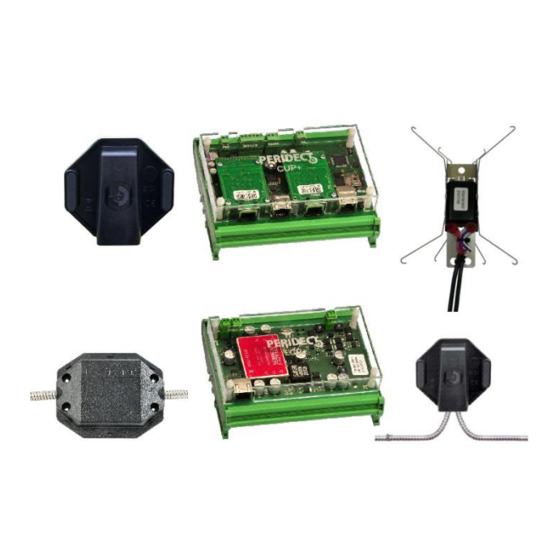
Page 5: Standard Version
DSP+ contains a sensor fitted in a protective casing. This sensor detects mechanical shocks of the fence via piezoelectric converters. The shocks are digitised, pre-processed by the sensor's microprocessor and delivered using digital sub transfer to the LCP+ module for further processing and finally to the CUP+ evaluation unit. -
Page 6: Antivandal Version
2.1.2. Antivandal Version This version features increased resistance to cable damage, e.g. being cut by the intruder or bitten apart by animals. The twin core cable is positioned in a stainless steel protection tube that secures the mechanical protection of the cable. The protection tube can also act as shielding in places with high-intensity electromagnetic interference (such as direct exposure to radar radiation). -
Page 7: Hidden Version
2.1.3. Hidden Version The Hidden version is designed for situations where it is necessary that the fence cannot be identified as security-protected. The detectors are installed inside the posts. Interconnecting cables in the protector are also led through the posts and underground in between the posts (alternatively on the foundation wall or the fence frame). - Page 8 2.1.4. Installing the Line on the Fence For the installation it is necessary to plan preliminary the detectors addressing as per the disposition of the object to be secured. The detectors are delivered with the addresses already in the lines with the maximum number of the detectors in one line according to the version of the product. The first and the last detector of the line have the ID number (address) stuck on the lid of the detector´s casing.
- Page 9 Detector placement and the method of running the cables across the fence Inner arrangement of the detector - 8 -...
-
Page 10: Cup+ – Control Unit Peridect
2.2. CUP+ – Control Unit PERIDECT+ The control unit processes the signals acquired from individual LCP+ line modules to which all DSP+ and LIP+ modules are connected. It evaluates the events of the individual detectors based on an internal algorithm and subsequently controls related actions, inputs switching, camera control and sending data into the SW superstructures. -
Page 11: Connecting The Cup+ Terminal Board
2.2.1. Connecting the CUP+ Terminal Board RS 485 data line – brought out at two places in parallel: As a system connector for service interventions and onto the terminal board with screwed terminals for permanent installation. Just one line may be connected at a time. - Page 12 UC – power voltage Output terminals, for detailed RS485 9 – 16V DC connection see picture below 1 2 3 4 5 6 0V + - Schematic internal connection of CUP+’s outputs and their assignment to connectors - 11 -...
-
Page 13: Lcp+ – Line Controller Peridect
2.3. LCP+ – Line Controller PERIDECT+ LCP+ line controller creates a communication interface for all line modules. This line is used for both powering and communication of the modules. The communication is carried out based on the principle of regular query where LCP+ receives information from individual modules of the line to process them and send the results to the CUP+ control unit using the RS232 serial interface. -
Page 14: Led Signalling Of Cup+ And Lcp
2.3.2. LED Signalling of CUP+ and LCP+ Flashing yellow led on the CUP+ indicates the processor is running and all the internal processes of the unit are operating properly. Flashing green led on the LCP+ indicates the processor is running and all the internal processes of the module are operating properly. -
Page 15: Connecting The Iop+ Terminal Board
The overvoltage module should be installed in regular span along the whole detection line. A detection line of maximum length should be fitted with 15–25 modules. 2.6. The IOP+/LAN/RS485 I/O Module of PERIDECT+ An output module used to control external devices, as well as indicate malfunction or alarm statuses. -
Page 16: Lsp+ – Line Separator Peridect
2.7. LSP+ – Line Separator PERIDECT+ The line separator is placed in the same casing as the detector. Its purpose is to separate/disconnect a part of the line that experiences a change in terms of electrical wiring parameters such as short circuit, lead-in etc. The part is disconnected by insulators while the rest of the line remains operational. -
Page 17: Technical Specification Of Peridect
3. Technical Specification of PERIDECT+ 3.1. CUP+ Control Unit PERIDECT+ Supply voltage: 9 – 16 VDC Consumption: 160 mA Operational temperature range: -40°C to +80°C Inputs: 1x tamper contact Outputs: 4x open collector type Protection: IP20 Dimensions: 150 x 100 x 40 mm 3.2. -
Page 18: Peridect+ Iop+/Lan I/O Module
3.6. PERIDECT+ IOP+/LAN I/O Module Supply voltage: 9 – 16 VDC Consumption: 120 mA (620 mA at all relays switched on) Operational temperature range: -25°C to +60°C Protection: IP20 Dimensions: 190 x 130 x 50 mm In case of connecting Expander module, it is necessary to connect it ONLY when the IOP module is powered off.
Need help?
Do you have a question about the Peridect+ and is the answer not in the manual?
Questions and answers